技術資料 タイミングベルト・タイミングプーリ 設計資料
ガイドフランジ
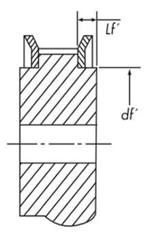
標準フランジを使用する時のプーリ寸法
フランジかん合部の寸法許容差
| かん合部寸法 df' | 25以下 | 25をこえ50以下 | 50をこえ100以下 | 100をこえ180以下 |
|---|---|---|---|---|
| 許容差 mm | -0.02 -0.05 |
-0.02 -0.06 |
-0.02 -0.07 |
-0.02 -0.12 |
段付部長さ
| 種類(ピッチ) | P3M | P5M | P8M | P14M |
|---|---|---|---|---|
| 段付部長さ Lf' mm | 2.0 | 2.2 | 2.6 | 5.0 |
フランジの表示方法
AS形...材質アルミ
SS形...材質スチール
AF形...材質アルミ
SF形...材質スチール
AF形...材質アルミ
SF形...材質スチール
表示例

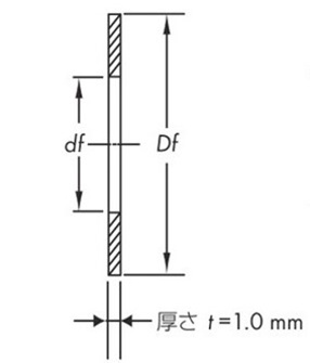
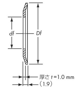
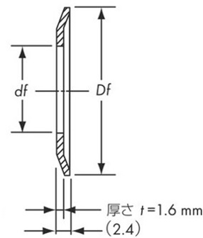
一般形状および基準寸法
| 種類 (ピッチ) |
厚さ t | 外径 Df 最小値 |
内径 df |
||
|---|---|---|---|---|---|
| 推奨値 | 通常使われる厚さ | ||||
| プレスタイプ | 切削タイプ | ||||
| P2M | 1.0 | 1.6 | 1.0 ~ 1.6 | Do + 4 | Do - 5 |
| P3M | Do + 4.5 | ||||
| P5M | 2.0 | 1.0 ~ 2.0 | Do + 6.3 | Do - 8 | |
| P8M | 1.6 | 2.5 | 1.6 ~ 2.5 | Do + 8 | Do - 10 |
| P14M | - | 4.0 | 4.0 ~ 5.0 | Do + 14 | Do - 20 |
使用する標準フランジによっては、外径または内径が上表と異なる場合があります。
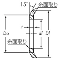
プレスタイプ
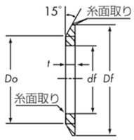
切削タイプ
ガイドフランジの取付け
フランジの固定
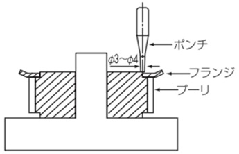
カシメ方式
通常プレスフランジおよび切削フランジは、下図のようにポンチでカシメて固定します。
そのときのカシメ数は次の基準に従ってください。
| 歯先円直径 mm | 30以下 | 30をこえ50以下 | 50をこえ120以下 | 120をこえ250以下 |
|---|---|---|---|---|
| カシメ数 | 4 | 8 | 12 | 16 |
注意
- ・平らな盤上にプーリを置き、カシメポンチでフランジをカシメてください。
- ・ハブと反対側をカシメる時は盤上に置いた円筒状の治具等にハブ部を挿入し、安定した状態でカシメてください。
その他の固定方法
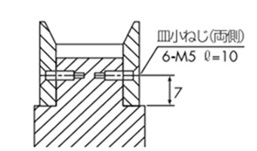
ねじ止め方式
P8M、P14Mなどの大歯数プーリの旋削フランジは、使い方によってプーリ本体と皿小ねじによって固定する場合もあります。
下表の皿小ねじ本数は、最小本数です。
| 歯先円直径 mm | 120以下 | 120をこえ250以下 | 250をこえ450以下 | 450をこえ650以下 |
|---|---|---|---|---|
| ねじ本数 | 4 | 6 | 8 | 12 |
ローレット方式
旋盤でローレットをかけてカシメる方式も使われます。
プーリの歯幅
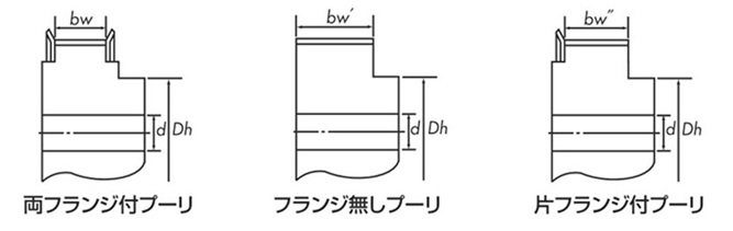
ベルト幅とプーリ歯幅
| 種類 (ピッチ) |
ベルト幅 mm |
プーリ歯幅(基準値) | ||
|---|---|---|---|---|
| 両フランジ付 bw |
フランジ無 bw' |
片フランジ付 bw'' |
||
| P2M | 4 | 5.0 | 9.0 | 7.0 |
| 6 | 7.5 | 11.5 | 9.5 | |
| 10 | 12.0 | 16.0 | 14.0 | |
| P3M | 6 | 7.5 | 11.5 | 9.5 |
| 10 | 12.0 | 16.0 | 14.0 | |
| 15 | 17.0 | 21.0 | 19.0 | |
| P5M | 10 | 11.6 | 16.0 | 13.8 |
| 15 | 16.6 | 21.0 | 18.8 | |
| 25 | 27.6 | 32.0 | 29.8 | |
| P8M | 15 | 16.8 | 22.0 | 19.4 |
| 25 | 27.8 | 33.0 | 30.4 | |
| 40 | 43.8 | 49.0 | 46.4 | |
| 60 | 64.8 | 70.0 | 67.4 | |
| P14M | 40 | 43.0 | 53.0 | 48.0 |
| 60 | 64.0 | 74.0 | 69.0 | |
| 80 | 85.0 | 95.0 | 90.0 | |
| 100 | 106.0 | 116.0 | 111.0 | |
| 120 | 127.0 | 137.0 | 132.0 | |
バックラッシレス歯形
タイミングベルトのかみ合いは通常バックラッシを設けてありますが、非常に正確な回転を要求されるロボット、電子部品組立機、NC装置、プリンター、プロッターなどのタイミングベルトドライブには、バックラッシを少なくして、回転角度誤差をおさえた特殊なバックラッシレス歯形によるプーリを製作しますのでご相談ください。
