技術資料 タイミングベルト・タイミングプーリ 設計資料
レイアウト設計
ガイドフランジの取付け
タイミングベルトは運転中にプーリの軸方向に片寄る性質があります。したがってタイミングベルトがプーリから外れないようにガイドフランジをプーリに取り付けます。ガイドフランジの設置基準は以下の通りです。
水平軸の伝動
一方のプーリの両側、または両方のプーリのそれぞれ反対側になるようにガイドフランジを取り付けてください。(例1)
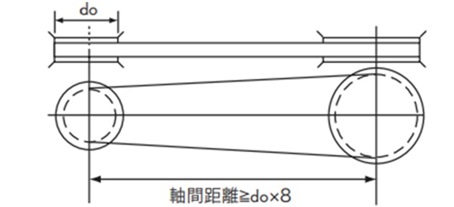
またプーリ軸間距離が小プーリの外径の8倍以上となる場合は、両方のプーリの両側にガイドフランジを付けてください。(例2)
(例1)
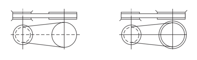
(例2)
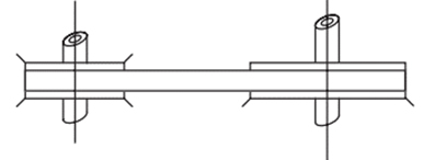
鉛直軸の伝動
ベルトは自重により下側に外れる恐れがあるので、一方のプーリの両側と他のプーリの下側にガイドフランジを付けてください。
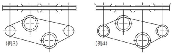
多軸伝動
プーリの1個おきに両側(例3)、または全プーリの片側の交互(例4)にガイドフランジを付けてください。
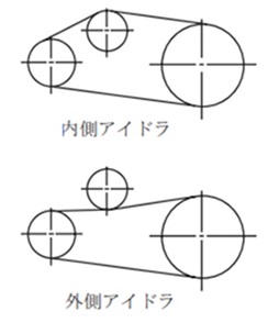
アイドラの使用
アイドラは次のような場合に使用します。
- ・軸受が固定で取付張力の調節用とする場合
- ・速比が大きく、小プーリのかみ合い歯数を大きくする場合
- ・駆動・従動プーリでベルトガイドができない場合
アイドラ使用上の注意
- ・アイドラは固定式とし、原則としてゆるみ側で使用してください。
- ・アイドラと両側との軸心平行度が悪いと、アイドラによってベルトがプーリから外れますので注意ください。
- ・アイドラの直径は下記により決めてください。
- 内側アイドラ...下表の最小プーリ歯数以上のタイミングプーリとします。
- 外側アイドラ...下表のプーリのピッチ円直径の1.2倍以上でクラウンのない平プーリとします。
アイドラ選定時の最小プーリ歯数
| 種類 | 回転速度 r/min | |||
|---|---|---|---|---|
| 900以下 | 900をこえ 1200以下 |
1200をこえ 1800以下 |
1800をこえ 3600以下 |
|
| P2M | 16 | 16 | 18 | 20 |
| P3M・UP3M | 14 | 14 | 16 | 18 |
| P5M・UP5M | 18 | 20 | 24 | 28 |
| P8M・UP8M | 24 | 26 | 26 | 28 |
| P14M・UP14M | 28 | 28 | 28 | 34 |
注)3600r/minをこえる場合は基準伝動容量表を参照ください。
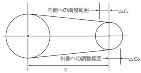
軸間距離調整しろ
アイドラを使用しない駆動・従動プーリだけの伝動では、ベルトの製作長さ(許容差)を含めて、軸受に軸間距離調整しろを設けてください。
2軸伝動の軸間距離調整しろ
| ベルト長さ | 種類 | ||
|---|---|---|---|
| P2M・P3M・P5M UP3M・UP5M |
P8M・P14M UP8M・UP14M |
||
| △Co | 500以下 | 3 | 3 |
| 500~1000 | 5 | 5 | |
| 1001~2000 | 10 | 10 | |
| 2000以上 | 15 | 15 | |
| △Ci | 共通 | 10 | 15 |
取付張力・軸荷重
ベルトの取付張力
タイミングベルト伝動はかみ合い伝動ですが、歯の乗り越え防止や円滑な伝動を行うためには、適切な取付張力が必要です。取付張力が弱い場合は、かみ合い不整合を生じ、また強い場合には騒音を発生することがあり、共に寿命を短くします。正確に張力を測定できる音波式ベルト張力計を用意していますのでご参照ください。
取付張力の与え方
- 1. アイドラ軸を含めて、すべての軸の平行度及びプーリのアライメントを正確に出します。
- 2. ベルトのスパンの中央に押し付け力(F)を加えます。
- 3. ベルトのたわみ(δ)がスパン100mm当たり1.6mmになるように張力を与えます。
押付力(F)の求め方
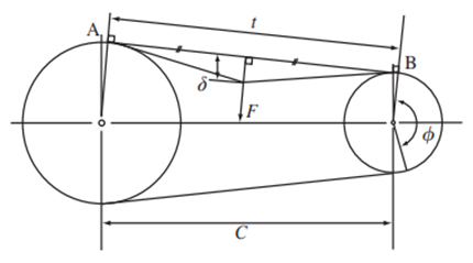
F = Ti + t × Y L 16
- F:スパンtの中央におけるたわみ(δ)に
必要な押付力 N{kgf} - Ti:取付張力 N{kgf}
- Y:補正係数
- δ:たわみ mm=0.016t
- t:スパン長さ mm
t = C2 - (Dp - dp)2 4
- C:軸間距離 mm
- Dp:大プーリのピッチ円直径 mm
- dp:小プーリピッチ円直径 mm
- L:ベルト長さ mm
軸荷重
軸荷重は次の式で求められます。
軸荷重 = 2Ti × sin Φ 2
- Ti:取付張力 N{kgf}
- Φ:プーリの巻付け角度 度
取付張力一覧
ウルトラPXベルト HC仕様
| 種類 (ピッチ) |
ベルト幅 mm |
取付張力 Ti N {kgf} | 補正係数 Y N {kgf} | |
|---|---|---|---|---|
| 推奨値 | 最大値 | |||
| UP3M-HC | 6 | 29 {3.0} | 40 {4.1} | 38.5 {3.9} |
| 10 | 52 {5.3} | 72 {7.3} | 61.8 {6.3} | |
| 15 | 82 {8.4} | 114 {11.6} | 90 {9.2} | |
| UP5M-HC | 10 | 108 {11.0} | 147 {15.0} | 102.7 {10.5} |
| 15 | 171 {17.4} | 232 {23.7} | 152 {15.5} | |
| 20 | 238 {24.3} | 323 {32.9} | 200.7 {20.5} | |
| 25 | 307 {31.3} | 418 {42.6} | 249.1 {25.4} | |
| 30 | 377 {38.4} | 513 {52.3} | 297.2 {30.3} | |
| 35 | 450 {45.9} | 613 {62.5} | 344.9 {35.2} | |
| 40 | 524 {53.4} | 713 {72.7} | 392.5 {40.0} | |
| UP8M-HC | 15 | 177 {18.0} | 235 {24.0} | 190.6 {19.4} |
| 20 | 244 {24.9} | 324 {33.0} | 246 {25.1} | |
| 25 | 317 {32.3} | 421 {42.9} | 299.9 {30.6} | |
| 30 | 389 {39.7} | 517 {52.7} | 352.6 {36.0} | |
| 35 | 464 {47.3} | 616 {62.8} | 404.3 {41.2} | |
| 40 | 540 {55.1} | 717 {73.1} | 455.1 {46.4} | |
| 45 | 618 {63.0} | 820 {83.6} | 505.2 {51.5} | |
| 50 | 697 {71.1} | 926 {94.4} | 554.7 {56.6} | |
| 55 | 777 {79.2} | 1032 {105.2} | 603.7 {61.6} | |
| 60 | 859 {87.6} | 1140 {116.2} | 652.2 {66.5} | |
| UP14M-HC | 40 | 794 {81.0} | 1050 {107.1} | 834 {85.0} |
| 60 | 1255 {128.0} | 1659 {169.2} | 1242.7 {126.7} | |
| 80 | 1747 {178.1} | 2310 {235.6} | 1649.0 {168.2} | |
| 100 | 2255 {229.9} | 2982 {304.1} | 2053.6 {209.4} | |
| 120 | 2771 {282.6} | 3665 {373.7} | 2456.9 {250.5} | |
ウルトラPXベルト HA仕様
| 種類 (ピッチ) |
ベルト幅 mm |
取付張力 Ti N {kgf} | 補正係数 Y N {kgf} | |
|---|---|---|---|---|
| 推奨値 | 最大値 | |||
| UP5M-HA | 10 | 108 {11.0} | 147 {15.0} | 102.7 {10.5} |
| 15 | 171 {17.4} | 232 {23.7} | 152.0 {15.5} | |
| 20 | 238 {24.3} | 323 {32.9} | 200.7 {20.5} | |
| 25 | 307 {31.3} | 418 {42.6} | 249.1 {25.4} | |
| 30 | 377 {38.4} | 513 {52.3} | 297.2 {30.3} | |
| 35 | 450 {45.9} | 613 {62.5} | 344.9 {35.2} | |
| 40 | 524 {53.4} | 713 {72.7} | 392.5 {40.0} | |
| UP8M-HA | 15 | 177 {18.0} | 235 {24.0} | 190.6 {19.4} |
| 20 | 244 {24.9} | 324 {33.0} | 246.0 {25.1} | |
| 25 | 317 {32.3} | 421 {42.9} | 299.9 {30.6} | |
| 30 | 389 {39.7} | 517 {52.7} | 352.6 {36.0} | |
| 35 | 464 {47.3} | 616 {62.8} | 404.3 {41.2} | |
| 40 | 540 {55.1} | 717 {73.1} | 455.1 {46.4} | |
| 45 | 618 {63.0} | 820 {83.6} | 505.2 {51.5} | |
| 50 | 697 {71.1} | 926 {94.4} | 554.7 {56.6} | |
| 55 | 777 {79.2} | 1032 {105.2} | 603.7 {61.6} | |
| 60 | 859 {87.6} | 1140 {116.2} | 652.2 {66.5} | |
| UP14M-HA | 40 | 794 {81.0} | 1050 {107.1} | 834.0 {85.0} |
| 60 | 1255 {128.0} | 1659 {169.2} | 1242.7 {126.7} | |
| 80 | 1747 {178.1} | 2310 {235.6} | 1649.0 {168.2} | |
| 100 | 2255 {229.9} | 2982 {304.1} | 2053.6 {209.4} | |
| 120 | 2771 {282.6} | 3665 {373.7} | 2456.9 {250.5} | |
ウルトラPXベルト HY仕様
| 種類 (ピッチ) |
ベルト幅 mm |
取付張力 Ti N {kgf} | 補正係数 Y N {kgf} | |
|---|---|---|---|---|
| 推奨値 | 最大値 | |||
| UP3M-HY | 6 | 39 {4.0} | 47 {4.8} | 76.0 {7.7 } |
| 10 | 68 {6.9} | 82 {8.4} | 118.2 {12.1} | |
| 15 | 105 {10.7} | 127 {13.0} | 167.7 {17.1} | |
| UP5M-HY | 10 | 125 {12.7} | 165 {16.8} | 152.5 {15.6} |
| 15 | 194 {19.8} | 256 {26.1} | 223.7 {22.8 } | |
| 20 | 265 {27.0} | 350 {35.7} | 293.6 {29.9} | |
| 25 | 338 {34.5} | 446 {45.5} | 362.6 {37.0 } | |
| 30 | 413 {42.1} | 545 {55.6} | 430.8 {43.9 } | |
| 35 | 488 {49.8} | 644 {65.7} | 498.4 {50.8 } | |
| 40 | 564 {57.5} | 744 {75.9} | 565.4 {57.7 } | |
| UP8M-HY | 15 | 255 {26.0} | 290 {29.6} | 272.0 {27.7 } |
| 20 | 347 {35.4} | 394 {40.2} | 341.3 {34.8 } | |
| 25 | 444 {45.3} | 505 {51.5} | 406.9 {41.5 } | |
| 30 | 541 {55.2} | 615 {62.7} | 469.9 {47.9} | |
| 35 | 640 {65.3} | 728 {74.2} | 530.6 {54.1 } | |
| 40 | 740 {75.5} | 841 {85.8} | 589.6 {60.1 } | |
| 45 | 842 {85.9} | 957 {97.6} | 647.0 {66.0 } | |
| 50 | 944 {96.3} | 1073 {109.4} | 703.0 {71.7} | |
| 55 | 1048 {106.9} | 1192 {121.6} | 757.9 {77.3} | |
| 60 | 1150 {117.3} | 1308 {133.4} | 811.8 {82.8} | |
| UP14M-HY | 40 | 1020 {104.0} | 1225 {124.9} | 1044.3 {106.5} |
| 60 | 1581 {161.2} | 1899 {193.6} | 1537.5 {156.8} | |
| 80 | 2162 {220.5} | 2597 {264.8} | 2023.1 {206.3} | |
| 100 | 2754 {280.8} | 3308 {337.3} | 2053.1 {209.4} | |
| 120 | 3366 {343.2} | 4043 {412.3} | 2978.6 {303.7} | |
PXベルト シナヤカ530(エンドレスベルト用)
| 種類 (ピッチ) |
ベルト幅 mm |
取付張力 Ti N {kgf} | 補正係数 Y N {kgf} | |
|---|---|---|---|---|
| 推奨値 | 最大値 | |||
| P2M-530 | 4 | 5.9 {0.6} | 7.8 {0.8} | 10.0 {1.0 } |
| 6 | 9.4 {1.0} | 12 {1.2} | 16.1 {1.6} | |
| 10 | 17 {1.7} | 22 {2.2} | 28.2 {2.9} | |
| P3M-530 | 6 | 20 {2.0} | 26 {2.7} | 17.6 {1.8} |
| 10 | 36 {3.7} | 47 {4.8} | 29.0 {3.0 } | |
| 15 | 57 {5.8} | 74 {7.5} | 43.1 {4.4 } | |
PXベルト(ロングベルト用)
| 種類 (ピッチ) |
ベルト幅 mm |
取付張力 Ti N {kgf} | 補正係数 Y N {kgf} | |
|---|---|---|---|---|
| 推奨値 | 最大値 | |||
| P2M | 4 | 5.9 {0.6} | 7.8 {0.8} | 10.0 {1.0 } |
| 6 | 9.4 {1.0} | 12 {1.2} | 16.1 {1.6 } | |
| 10 | 17 {1.7} | 22 {2.2} | 28.2 {2.9} | |
| P3M | 6 | 20 {2.0} | 26 {2.7} | 17.6 {1.8 } |
| 10 | 36 {3.7} | 47 {4.8} | 29.0 {3.0} | |
| 15 | 57 {5.8} | 74 {7.5} | 43.1 {4.4} | |
PXベルト RC仕様
| 種類 (ピッチ) |
ベルト幅 mm |
取付張力 Ti N {kgf} | 補正係数 Y N {kgf} | |
|---|---|---|---|---|
| 推奨値 | 最大値 | |||
| P2M-RC | 4 | 5.9 {0.6} | 7.8 {0.8} | 10.0 {1.0} |
| 6 | 9.4 {1.0} | 12 {1.2} | 16.1 {1.6} | |
| 10 | 17 {1.7} | 22 {2.2} | 28.2 {2.9} | |
| P3M-RC | 6 | 20 {2.0} | 26 {2.7} | 17.6 {1.8} |
| 10 | 36 {3.7} | 47 {4.8} | 29.0 {3.0} | |
| 15 | 57 {5.8} | 74 {7.5} | 43.1 {4.4} | |
| P5M-RC | 10 | 97 {9.9} | 132 {13.5} | 56.9 {5.8} |
| 15 | 154 {15.7} | 209 {21.3} | 82.4 {8.4} | |
| 20 | 214 {21.8} | 291 {29.6} | 139.0 {14.2} | |
| 25 | 276 {28.2} | 376 {38.4} | 201.0 {20.5} | |
| P8M-RC | 15 | 203 {20.6} | 265 {27.0} | 151.3 {15.4} |
| 20 | 280 {28.5} | 365 {37.3} | 193.0 {19.7} | |
| 25 | 363 {37.0} | 473 {48.3} | 233.0 {23.8} | |
| 40 | 617 {63.0} | 807 {82.3} | 346.6 {35.3} | |
| 60 | 982 {100.1} | 1283 {130.9} | 488.3 {49.8} | |
| P14M-RC | 40 | 990 {101.0} | 1310 {133.6} | 635.5 {64.8} |
| 60 | 1564 {159.5} | 2070 {211.1} | 973.2 {99.2} | |
| 80 | 2178 {222.1} | 2882 {293.9} | 1316.8 {134.3} | |
| 100 | 2812 {286.7} | 3720 {379.3} | 1664.9 {169.8} | |
| 120 | 3455 {352.3} | 4572 {466.2} | 2016.6 {205.6} | |
PXベルト
| 種類 (ピッチ) |
ベルト幅 mm |
取付張力 Ti N {kgf} | 補正係数 Y N {kgf} | |
|---|---|---|---|---|
| 推奨値 | 最大値 | |||
| P5M | 10 | 108 {11.0} | 147 {15.0} | 56.9 {5.8} |
| 15 | 171 {17.4} | 232 {23.7} | 82.4 {8.4} | |
| 20 | 238 {24.3} | 323 {32.9} | 139.0 {14.2} | |
| 25 | 307 {31.3} | 418 {42.6} | 201.0 {20.5} | |
| P8M | 15 | 225 {22.9} | 294 {30.0} | 151.3 {15.4} |
| 20 | 311 {31.7} | 406 {41.4} | 193.0 {19.7} | |
| 25 | 403 {41.1} | 526 {53.6} | 233.0 {23.8} | |
| 40 | 686 {70.0} | 897 {91.5} | 346.6 {35.3} | |
| 60 | 1091 {111.3} | 1426 {145.4} | 488.3 {49.8} | |
| P14M | 40 | 990 {101.0} | 1310 {133.6} | 635.5 {64.8} |
| 60 | 1564 {159.5} | 2070 {211.1} | 973.2 {99.2} | |
| 80 | 2178 {222.1} | 2882 {293.9} | 1316.8 {134.3} | |
| 100 | 2812 {286.7} | 3720 {379.3} | 1664.9 {169.8} | |
| 120 | 3455 {352.3} | 4572 {466.2} | 2016.6 {205.6} | |
PXベルト(耐水仕様)
| 種類 (ピッチ) |
ベルト幅 mm |
取付張力 Ti N {kgf} | 補正係数 Y N {kgf} | |
|---|---|---|---|---|
| 推奨値 | 最大値 | |||
| P5M-W | 10 | 108 {11.0} | 147 {15.0} | 50.1 {5.1} |
| 15 | 171 {17.4} | 232 {23.7} | 74.2 {7.6} | |
| 25 | 307 {31.3} | 418 {42.6} | 184.9 {18.9} | |
| P8M-W | 15 | 225 {22.9} | 294 {30.0} | 147.2 {15.0} |
| 25 | 403 {41.1} | 526 {53.6} | 226.7 {23.1} | |
| 40 | 686 {70.0} | 897 {91.5} | 337.3 {34.4} | |
| 60 | 1091 {111.3} | 1426 {145.4} | 475.2 {48.5} | |
プーリのアライメント
タイミングベルトは、プーリのアライメントが正しい場合でもプーリの中央で回転せず、どちらかに片寄る性質があります。その力は非常に弱いものですが、プーリのアライメントが悪いと、ベルトはプーリフランジに強く押し付けられ、破損、切断します。したがってプーリアライメントは下表の許容差内に調整してください。
プーリのアライメント許容差
| ベルトサイズ | 全品種 | |||
|---|---|---|---|---|
| ベルト幅 mm | 30以下 | 30~50 | 50~100 | 100以上 |
| 許容平行度 | 51000以下 | 41000以下 | 31000以下 | 21000以下 |
| θ分 | 17以下 | 13以下 | 10以下 | 6以下 |
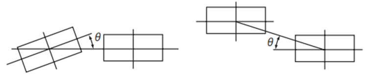
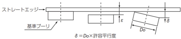
プーリの調整方法
図のように基準となるプーリにストレートエッジをあて、他のプーリをストレートエッジに全面で接触させること(ε=0とする)によりプーリを正しい位置に並べることができます。
また図のδを限度以下にすることにより軸の平行度を同時に出すことができます。
ロングベルト
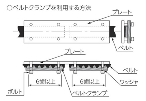
接続方法
ベルト寸法許容差
ベルト長さの許容差
| PXベルト ウルトラPXベルト |
許容差 |
|---|---|
| 256以下 | ±0.41 |
| 256をこえ3384以下 | ±0.46 |
| 384をこえ3512以下 | ±0.51 |
| 512をこえ3760以下 | ±0.61 |
| 760をこえ1016以下 | ±0.66 |
| 1016をこえ1272以下 | ±0.76 |
| 1272をこえ1528以下 | ±0.81 |
| 1528をこえ1776以下 | ±0.86 |
| 1776をこえ2032以下 | ±0.91 |
| 2032をこえ2288以下 | ±0.97 |
| 2288をこえ2544以下 | ±1.02 |
| 2544をこえ2792以下 | ±1.07 |
| 2792をこえ3048以下 | ±1.12 |
| 3048をこえ3304以下 | ±1.17 |
| 3304をこえ3560以下 | ±1.22 |
| 3560をこえ3808以下 | ±1.26 |
| 3808をこえ4064以下 | ±1.32 |
| 4064をこえ4320以下 | ±1.37 |
| 4320をこえ4576以下 | ±1.42 |
ベルト幅の許容差
| ベルト幅 | ベルト長さ | ||
|---|---|---|---|
| 840以下 | 840をこえ 1680以下 |
1680を こえるもの |
|
| 10以下 | +0.3 -0.6 |
+0.6 -0.6 |
- |
| 10をこえ45以下 | +0.8 -0.8 |
+0.8 -1.2 |
+0.8 -1.2 |
| 45をこえ75以下 | +1.2 -1.6 |
+1.6 -1.6 |
+1.6 -1.6 |
| 75をこえ100以下 | +1.6 -1.6 |
+1.6 -2.0 |
+2.0 -2.0 |
| 100をこえるもの | +2.4 -2.4 |
+2.4 -2.8 |
+2.4 -3.2 |
プーリの材料・単位質量
プーリの材質は次のものが適しています。
プーリの材料・単位質量
| 材質 | 材質記号 | 単位質量 |
|---|---|---|
| 機械構造用炭素鋼 | S45C | 7.85 |
| アルミニウム合金 | A2017-T4 | 2.8 |
| ステンレス鋼 | SUS304 | 7.8 |
プーリ設計の一般式
・ピッチ円直径 Dp = N × p π
・歯先円直径 Do = Dp - 2a = N × p π -2a
- p:ベルトピッチ mm
- N:プーリ歯数
- a:ピッチライン深さ(PLD)mm
| P3M | P5M | P8M | P14M | |
|---|---|---|---|---|
| p ピッチ | 3 | 5 | 8 | 14 |
| a(PLD) | 0.381 | 0.571 | 0.686 | 1.397 |
※カタログ内P14M標準プーリの歯先円直径は補正値を含んでいますので、この式の通りにならないものがあります。
プーリ各部寸法の許容値
歯すじ方向の誤差(仕上軸穴中心線に対して)
歯と軸穴中心線の平行度
| 使用ベルト幅 | 歯スジ方向誤差の許容値 |
|---|---|
| 50以下 | 0.03 |
| 50をこえ100以下 | 0.04 |
| 100をこえるもの | 0.05 |
歯先円周の振れ(仕上軸穴中心線に対して)
| 歯先円直径 | 許容振れ |
|---|---|
| 203.20以下 | 0.13 |
| 203.20をこえるもの | 0.13 + [(歯先円直径 - 203.20)×0.0005] |
側面の振れ(仕上軸穴中心線に対して)
| 歯先円直径 | 許容振れ |
|---|---|
| 101.60以下 | 0.1 |
| 101.60をこえ254.00以下 | 歯先円直径×0.001 |
| 254.00をこえるもの | 0.25 + [(歯先円直径 - 254.00)×0.0005] |
歯先円筒の円筒度(勾配 = テーパ×1/2)
| プーリの呼び幅 | 円筒度の許容値 |
|---|---|
| 20以下 | 0.01 |
| 20をこえ50以下 | 0.02 |
| 50をこえ100以下 | 0.04 |
| 100をこえるもの | 0.06 |
- ・上記許容値は切削加工のものです。
- ・成型のプーリについては使用条件、レイアウトにより異なりますので当社へご相談ください。
