技術資料 直動機器 ジップチェーンアクチュエータ選定
選定表
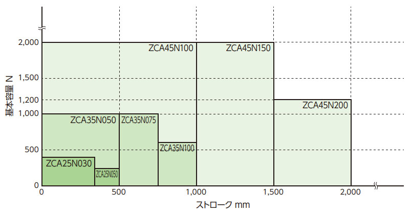
右のグラフはストロークと基本容量との関係を表しています。
このグラフでZCA1台当たりの必要推力と使用ストロークを確認し、形番を決定してください。
詳細な検討が必要な場合、下記の計算にてご確認ください。
選定方法
使用機械 ..... 機械構成、ZCAの使用台数、使用環境etc
負荷 ..... 負荷の性質、負荷またはワークの質量、駆動源、駆動方法etc
取付形状 ..... 取付方向(押上、水平、吊下)、直線ガイドの方式
稼働速度 ..... ZCA必要速度
ストローク ..... 実際に使用するストローク
1. 補正荷重Fsの算出
負荷の性質を考慮し、使用係数(表1)を参照の上、補正荷重Fsを求めます。
補正荷重 Fs N{kgf} = 必要推力 P N{kgf}×使用係数 Sf
表1 使用係数
| 負荷の性質 | 使用例 | 使用係数 Sf |
|---|---|---|
| 衝撃のない円滑な作動 負荷慣性 小 |
コンベヤの切り替え | 1.0~1.3 |
| 軽い衝撃のある作動 負荷慣性 中 |
各種移載装置 各種リフター昇降 |
1.3~1.5 |
2. 1台当たりの必要推力Fs1の算出
補正荷重Fsより1台あたりの必要推力Fs1を求めます。
連動運転の場合は連動係数(表2)を参照の上、計算します。
ZCA1台当たりの推力 Fs1 N{kgf} = 補正荷重 Fs N{kgf} ÷(連動台数×連動係数 Fg)
表2 連動係数
| 連動台数(台) | 1台 | 2台 | 4台 |
|---|---|---|---|
| 連動係数 Fg | 1.0 | 0.83 | 0.69 |
3.駆動部無とハイポイドモートル付もしくはTERVO付のいずれかを選択
4. 形番を仮選定
機種一覧より、1台当たりの推力Fs1がZCAの基本容量以下であることを確認します。ストロークは使用ストロークに余裕を見込んでください。
[駆動部無を選択した場合]
機種一覧より、1台当たりの推力および許容ストロークより形番を仮選定します。5項以降に進んでください。
[ハイポイドモートル付・TERVO付を選択した場合]
機種一覧より、1台当たりの推力、チェーン稼働速度および許容ストロークを満足する形番を仮選定します。
5. 最大速度
最大速度以下であることを確認します。
6. 必要入力回転速度の確認
稼働速度より、必要入力回転速度を求めます。
N = V×60/K N:入力回転速度r/min V:稼働速度 mm/s K:入力軸1回転当りのジップチェーン移動量 mm (表3)
7. 必要入力トルクの確認
必要入力トルクを計算します。
T = Fs1×Dp 2×1000×η + To
T:必要入力トルク N・m{kgf・m}
Fs1:1台当たりの必要推力 N{kgf}
Dp:スプロケットのピッチ円直径 mm (表3)
η:ZCAの総合効率 (表3)
To:平均無負荷稼働トルク N・m{kgf・m} (表3)
表3 能力表
| 形式 | ZCA25 | ZCA35 | ZCA45 |
|---|---|---|---|
| 総合効率 η | 90% | 90% | 90% |
| ※平均無負荷稼働トルク To N・m{kgf・m} | 0.62{0.063} | 1.63{0.17} | 5.85{0.6} |
| 入力軸1回転当り移動量 K mm | 95.3 | 142.9 | 240 |
| スプロケットのピッチ円直径 Dp mm | Φ30.92 | Φ46.48 | Φ78.0 |
※無負荷時に入力軸を連続回転するのに必要なトルクの平均値です。
チェーンの1ピッチごとに、噛合いによるトルク変動があります。
8. 許容オーバハングロードの検討
軸をチェーン、ギヤ、歯付ベルト、Vベルトなどで駆動する場合オーバハングロードが許容値以下であるかを確認します。
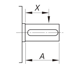
O.H.L.:オーバハングロード N{kgf}
f:伝動要素係数 (表4)
Lf:荷重の作用位置による係数 (表5)
T:必要入力トルク N・m{kgf・m}
D:スプロケット、ギヤ、プーリなどのピッチ円直径 m
許容O.H.L. ≧ 2×T×f×Lf D
表4 伝動要素係数 (f)
| チェーン | ギヤ 歯付ベルト | Vベルト |
|---|---|---|
| 1.0 | 1.25 | 1.5 |
表5 荷重の作用位置による係数 (Lf)
| X/A | 0.25 | 0.5 | 0.75 | 1.0 |
|---|---|---|---|---|
| Lf | 0.9 | 1.0 | 1.15 | 1.25 |
表6 許容オーバハングロード
| 形式 | ZCA25 | ZCA35 | ZCA45 |
|---|---|---|---|
| 許容オーバハングロード N{kgf} | 638{65.0} | 946{96.4} | 2065{210.5} |
9.オプションの選択
使用条件に合わせてオプションを選定します。
- ・取付ベース
- ・キャップ
- ・ジャバラ
- ・給脂プレート
10.形番の決定
11.必要入力容量の算出(モータ無の場合)
必要入力容量 P kW = T×N/9550
注意:
必要入力トルクの内、平均無負荷稼働トルクが占める割合が25%以上となる場合、チェーン特有の噛合い動作によるトルク変動の影響が大きくなります。円滑に稼働させるために、平均無負荷稼働トルク(表3)を1.5倍にて選定ください。
必要入力トルク選定時の注意
ZCAの配置が下図のようにストレート形の場合、駆動源による入力トルクが許容入力軸トルク以下であることをご確認ください。
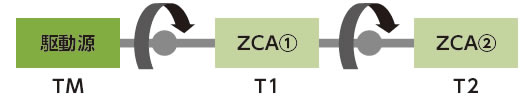
駆動源側のZCA (1)には2台分の必要入力トルクが入力軸に伝達されます。
この2台分のトルクが許容入力軸トルク以下であることを確認してください。
ZCA (1)のみの必要な入力トルク T1
ZCA (2)のみの必要な入力トルク T2
駆動源必要トルクTM = T1 + T2 < 許容入力軸トルク
選定例
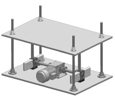
使用機械 ..... 昇降装置 ZCA2台使用、工場内(常温、粉塵なし)
必要推力 ..... 軽い衝撃がある、1200N{122kgf}/2台、ブレーキ付小形ギヤモータは別置きとしてカップリングで連結
取付形状 ..... ガイドポール4本(押上で使用)
稼働速度 ..... 250mm/s((定速:加減速を見込まず)
ストローク ..... 450mm
電源 ..... 200V/60Hz
| SI単位 |
|---|
ZCA
モータ(60Hz)
カップリング
|
| {重力単位} |
|---|
ZCA
モータ(60Hz)
カップリング
|
位置制御が必要な場合はエンコーダ付モータもしくはサーボモータをご使用ください。
(エンコーダ付モータを希望される場合は別途ご相談ください。)
選定例は一例ですのでカップリング、マイタギヤボックス、モータの選定時は専用カタログをご参照ください。
駆動部
ハイポイドモートルTA・TRシリーズ

- ・高効率のハイポイドギヤを採用し、高さ寸法を抑えたコンパクトな小形ギヤードモータです。
- ・独自のグリス漏れ対策で使いやすく、エンコーダ付仕様を併用すれば多点位置決め制御も簡単。
マイタギヤボックス
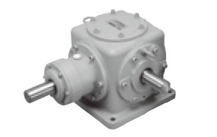
- ・マイタギヤボックスは複数のジップチェーンアクチュエータを同期運転する場合に使用します。
- ・サイズ、軸配置、速比、材質など標準機種で豊富なバリエーションを取り揃えています。
エクトフレックス®カップリング
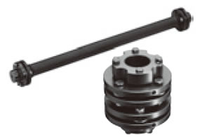
- ・無潤滑で高精度なカップリングで、サーボモータ駆動にも最適です。
- ・キー溝・クランプ・テーパロックなど豊富な軸締結方式と1㎜単位のきめ細かい軸穴加工に対応します。
