技術資料 直動機器 リニスピードジャッキ 取扱
ここでは、リニスピードジャッキに関する一般取扱について記載しています。
詳細につきましては、製品に同梱しています取扱説明書をご参照ください。
据付
ジャッキ取付面
ジャッキの取付面には、防錆目的で塗装しています。取付面に塗装が不要な場合は当社までお問合せください。
据付方向 [取付形式に従って各プラグの位置が異なります。]
取付形式と各プラグ(プレッシャベント、ドレンプラグ)の取付位置が正しいかご確認ください。
(詳細は各製品の主要諸元ページの外形寸法図をご確認ください。)
減速部はオイルを封入の上、出荷しています。運搬時の油漏れ防止のため、給油口はプラグで栓をしていますので、ご使用前にプラグ栓を付属のプレッシャベントに取換えてください。プラグ栓のままで運転をした場合、内圧が上昇し、オイルシール部から油が漏れるおそれがあります。
据付場所
ジャッキの周囲には通風を妨げるような障害物を置かないでください。冷却が阻害され、異常加熱によるやけど、火災のおそれがあります。ネジカバーやネジ軸を架台に通す穴はジャッキ据付面と架台の接触面を大きく取れるようできる限り小さな穴にしてください。
グリースやオイルが飛散、落下するおそれがあります。食品機械等で油気を嫌う装置には、グリースやオイルの飛散・落下に備えて、油受け等の損害防止装置を取付けてください。
取付ボルト
ジャッキのギヤケースにある4ヵ所の取付穴を利用し、取付ボルトを固定してください。 (取付ボルトは付属していません。)
ジャッキの取付ボルトサイズは下表をご参照ください。取付ボルトは通常の場合、強度区分10.9以上のものをご使用ください。
取付ボルト、取付穴サイズ
| 形式 | フェイスマウント | フランジマウント |
|---|---|---|
| SJ015H | M10 | Φ11 |
| SJ030H | M12 | Φ14 |
| SJ050H | M16 | Φ18 |
モータとの連結
ジャッキ本体の他、モータ等の据付時には、適正な据付が行えるよう、最大荷重が加わっても据付時の心出し精度が狂わない安全率を見込んだ強固な架台をご用意ください。また、入力軸に接続される伝動軸等の心出しを確実に行ってください。
フローティングシャフトで駆動する場合には、回転速度により、振動が発生するなど作動不良の原因になりますので、シャフトの剛性、カップリングのバックラッシを十分ご検討ください。
先端金具の取付け
ネジ軸に先端金具を取付ける場合には、軸端のネジ部に緩み止めを施してください。ネジ軸には回転トルクが働き、先端金具が抜け落ちますので下記内容を実施ください。
-
(1)ネジ緩み止め接着剤を塗布
ネジの緩み止めには、右記銘柄のもの、または相当品をご使用ください。接着剤塗布時には各メーカの取扱注意などを順守ください。
ネジ緩み止め接着剤
メーカ 銘柄 ヘンケルジャパン株式会社 #262、271 株式会社スリーボンド #1307N - (2)止めネジで固定
先端金具を締め込んだ後、緩み止めとして付属の止めネジ(六角穴付ボルト)で固定してください。
リミットスイッチの設定
ストロークを調整するために設置するリミットスイッチは、ジャッキの惰行量を見込んで設定ください。惰行量は据付状態、運搬物質量によって変わりますので、最大の惰行量を見込んでください。また、万が一のことを考慮して、ストローク範囲内に機械的なストッパー等をご設置ください。
位置検出ユニットの設定
オプションの位置検出ユニット(内部LS,ロータリエンコーダ、ポテンショメータ)をご使用の場合には、工場出荷段階でのストローク調整等は行っていませんので、運転前には必ず調整を行ってください。内部LS調整時には、ジャッキのストローク範囲を超えないように十分注意をしながら手動またはインチングにより作動させて設定ください。ストロークの限界を超えますとネジ軸の脱落やジャバラの破損などを起こしますのでご注意ください。
注意事項
- ⚠ (1)荷重が作用している状態で、入力軸から手動操作しないでください。荷重により入力軸が回され危険です。
- ⚠ (2)いかなる場合も当て止めは行わないでください。当て止めを行いますとジャッキ内部に重大な損傷を起こします。
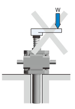
- ⚠ (3)ジャッキに加わる荷重は、ジャッキのネジ軸方向と同軸上に作用するようにしてください。作用方向や位置が不適切ですと、ジャッキに曲げ荷重や横荷重が加わり破損のおそれがあります。(図2)
横荷重などが加わる場合は、ガイドを設けてジャッキが直接横荷重や曲げモーメントを受けないようにご配慮ください。 - ⚠ (4)起動時のピークトルクが許容入力軸トルクを超えないようにご注意ください。
図2