技術資料 直動機器 リニパワージャッキ 技術資料
許容座屈荷重の計算式
ジャッキのネジ軸が許容できる座屈荷重は下記の式により計算します。
PCR = m×
d2
L
2
PCR > W×Sfとなるようにしてください。
PCR:許容座屈荷重 N{kgf}
d:ネジ谷底径 mm(各製品の主要諸元ページを参照ください。)
m:支持係数(下図より据付状態をお選びください。)
L:作用点間距離mm
(各枠番の寸法表のMAX寸法。先端金具を必要とする場合は先端金具の寸法をご参照ください。)
W:ジャッキ1台当たりの荷重 N{kgf}
Sf:座屈安全率(一般的には4)
据付状態

A ベース固定一軸端フリー
| m | |
|---|---|
| SI単位 | 2.5×10⁴ |
| 重力単位 | {2.5×10³} |

B 両端クレビス支持
| m | |
|---|---|
| SI単位 | 10×104 |
| 重力単位 | {10×103} |
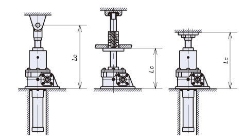
C ベース固定一軸端支持/固定
| m | |
|---|---|
| SI単位 | 20×104 |
| 重力単位 | {20×103} |
| SI単位 |
JWM100USH5JIを荷重49000N、据付状態C(ベース固定-軸端支持/固定)にて使用時のPCRを算出しますと
|
|---|
| {重力単位} |
JWM100USH5JIを荷重5000kgf、据付状態C(ベース固定-軸端支持/固定)にて使用時のPCRを算出しますと
|
|---|
