技術資料 高速リフタ リフトマスタモータ結線(200V級)
モータ結線(200V級) H速、U速の場合は昇降速度が速いため、インバータ制御にて加減速時間を設けてご使用願います。
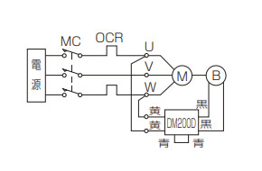
下図の正相接続におけるリフタの昇降方向は各寸法表をご確認ください。
| S速 | S速、H速、U速(インバータ駆動) | |
|---|---|---|
| ブレーキ同時切り | ブレーキ交流別操作 | ブレーキ交流別操作+直流別切り (停止精度を要求される場合) |
 |
 |
 |
[M]:モータ [B]:ブレーキ MC:電磁接触器 MCa:補助継電器 OCR:過電流継電器 DM200D:DCモジュール --N--:保護素子(バリスタ)
- 注1) ブレーキ電圧はDC90Vです。(DM200DにAC200V入力時)
- 注2) 直流別切りにてご使用の場合は、配線の長さ・配線の方法・リレーの種類などによってブレーキ用電源モジュールが破損する場合がありますので、直流別切り用端子間にバリスタを接続してください。
- 注3) 0.1kW~0.75kWの異電圧仕様(AC230V等)で交流別操作で使用される場合は、ブレーキへの供給電圧が異なりますので、お問合せください。
- 注4) ブレーキ電源は必ずインバータの一次側電源から取り、ブレーキ操作とモータのON・OFFとは必ず同期させてください。
- 注5) MCaの投入、開放はインバータとのインターロックが必要となりますので、インバータの取扱説明書をご参照ください。
- 注6) バリスタはブレーキ用電源モジュールの近く(青リード線部)に接続するほうが効果的です。具体的なバリスタの形番は下記の通りですが、相当品のバリスタでも使用可能です。バリスタ電圧はDM200Dは470Vのものを選定してください。
- ※1印部のブレーキの供給電圧は、0.1kW・0.2kWはAC200V~AC254V、0.4kW・0.75kWはAC200V~AC220V、1.5kW~2.2kWはAC200V~AC230Vとしてください。
- ※2の補助継電器(MCa)は接点容量AC200V7A以上(抵抗負荷)のものをご使用ください。
- ※3にMCの補助接点あるいは補助継電器をご使用の場合は接点容量AC200V10A以上(抵抗負荷)としてください。
| 商品名 | メーカ | 形番 |
|---|---|---|
| DM200Dの時 | ||
| サージアブソーバ | パナソニック(株) | ERZV14D471 |
| セラミックバリスタ | 日本ケミコン(株) | TND14V-471KB00AAA0 |
モータ特性
三相モータ付
| 相数 | 出力 | 極数 | 周波数 Hz | 電圧 V | 定格電流値 A | 交流側ブレーキ電流値 A(参考値) at 20℃ |
|---|---|---|---|---|---|---|
| 三相 | 0.1kW | 4 | 50/60/60 | 200/200/220 (400/400/440) |
0.63/0.57/0.58 (0.32/0.29/0.29) |
0.12 |
| 0.4kW |
2.3/2.0/2.0 (1.2/1.0/1.0) |
0.16 | ||||
| 0.75kW | 50/60/60 (50/50/60/60) |
200/200/220 (380/400/400/440) |
4.0/3.5/3.4 (1.9/2.0/1.75/1.7) |
0.17 | ||
| 1.5kW |
6.5/6.1/5.8 (3.5/3.5/3.2/3.1) |
0.10 | ||||
| 2.2kW |
10.6/9.1/9.1 (5.2/5.4/4.6/4.6) |
0.10 |
注)ブレーキ付の場合、ブレーキリード線がモータリード線に接続されている相は、上記ブレーキ電流が加算されます。
交流側ブレーキ電流値は、AC200V60Hz、AC100V60Hz時の値です。
サーボモータ付
サーボモータの特性については「標準機種一覧(こちら)」のサーボモータ形名をご確認の上、モータメーカより発行される資料をご参照ください。
