Technical Data  Locking Device  Sizing and procedure

To view selection procedures and precautions, please proceed to the following.

Click here to narrow down the product series or to make a tentative selection.

If you have specific conditions of use and wish to make a detailed selection, please click here.

Selection of SL series

1. Maximum Torque and Maximum Thrust

Calculate maximum torque and thrust based on transmissible capacity and safety factor f.

※For servo motor and stepping motor locking, use the maximum torque (peak torque) of each as the maximum torque to be generated (Tmax).

SI Unit

Tmax = 9550 × H n ・f

Tmax = Max. Generated Torque (N・m)

  • H:Transmission capacity (kW)
  • n:Rotational Speed of the Shaft with PL Installed (min-1)
  • f:Service factor
Gravity unit

Tmax = 974 × H n ・f

Tmax = Max. Generated Torque (kgf・m)

  • H:Transmission capacity (kW)
  • n:Rotation Speed of the Shaft with PL Installed (min-1)
  • f:Service factor

Pmax = Pax・f

  • Pmax:Max. Thrust Load kN{kgf}
  • Pax:Thrust load kN{kgf}
  • f:Service factor

f:Service factor

Load conditions Service factor
Load without shock Low inertia 1.5~2.5
Load with minor shock Medium inertia 2.0~4.0
Load with major shock High inertia 3.0~5.0

If only torque is applied

Compare the Tmax obtained from the above calculation with the catalog rated transmissible torque Mt.

Mt ≥ Tmax → Acceptable

Mt < Tmax → Use larger size.

If torque and thrust are applied simultaneously

Calculate the total load MR, and compare it with transmissible torque Mt.

MR = Tmax2 + (Pmax × d 2 )2

  • Tmax:Max. Generated Torque N・m{kgf・m}
  • Pmax:Max. Thrust Load N{kgf}
  • d:Shaft diameter m

Compare the MR obtained from the above calculation with the catalog rated transmissible torque Mt.

Mt ≥ MR → Acceptable

Mt < MR → Use larger size.

*Installing multiple units is not possible for this series.

2. Shaft and Hub

(1) Material Strength

Large contact pressure applies to both the shaft and hub during installation. Select shaft and hub materials that meet the following strength requirements.

σ0.2S ≧ 1.2 × P    σ0.2B ≧ 1.2 × P'

  • P :Shaft-side contact pressure MPa{kgf/mm2}
  • P':Hub-side contact pressure MPa{kgf/mm2}
  • σ 0.2S:Yield point of shaft material MPa{kgf/mm2}
  • σ 0.2B:Yield point of hub material MPa{kgf/mm2}

Please refer to the strength table for iron and steel materials, which shows the yield point values of typical steel materials.

(2) Hub Material Strength

Torque and contact pressure will combine and produce stress on the hub. Calculate this stress using one of the following formulas.

  • (a) Stress applied to the hub from a normal direction (σw)

    σW = - P MPa{kgf/mm2}

    P:Shaft-side contact pressure MPa{kgf/mm2}

  • (b) Stress applied to the hub from a tangential direction (σt)

    σt = P(1 + Q2) - 2 × P' 1 - Q2 MPa{kgf/mm2}

    Q = dW d

    P:Shaft-side contact pressure MPa{kgf/mm2}

    P':Contact pressure on the hub MPa{kgf/mm2}

    dW:Shaft diameter mm d:Hub outer diameter mm

  • (c) Shearing stress applied to the hub by torsional force (τB)

    τB = 1600 × Tmax・d π(d4 - dW4) MPa{kgf/mm2}

Make sure σ0.2B (yield point of the hub material) is greater than σv.

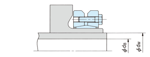
(3) Hollow Shaft Inner Diameter

Calculate the hollow shaft inner diameter using the following formula.

Hollow Shaft Inner Diameter

dB ≦ dW σ0.2S - 1.6 × P σ0.2S

  • dB:Maximum hollow shaft inner diameter mm
  • d:Shaft diameter mm
  • σ0.2S:Shaft material yield point MPa{kgf/mm2}
  • P:Shaft-side contact pressure MPa{kgf/mm2}