技術資料 パワーロック 選定と手順
選定手順や注意事項等をご覧になりたい方は下記へお進みください。
製品シリーズの絞り込みや仮選定をご希望の方は
こちらをクリックしてください。
使用条件が決まっており詳細な選定をご希望の方は
こちらをクリックしてください。
MLシリーズの選定
1. 最大発生トルクと最大発生スラスト荷重の確認
発生する伝達容量に使用係数を見込んで、最大発生トルクと最大発生スラスト荷重を求めます。
※サーボモータ・ステッピングモータの締結の場合は、それぞれの最大トルク(ピークトルク)を最大発生トルク(Tmax)としてください
| SI単位 |
|---|
|
Tmax = 9550 × H n ・f Tmax = 最大発生トルク(N・m)
|
| 重力単位 |
|---|
|
Tmax = 974 × H n ・f Tmax = 最大発生トルク(kgf・m)
|
Pmax = Pax・f
- Pmax:最大発生スラスト荷重 kN{kgf}
- Pax:スラスト荷重 kN{kgf}
- f:使用係数
f:使用係数
| 負荷の状態 | 使用係数 | |
|---|---|---|
| 衝撃のない円滑な負荷 | 慣性小 | 1.5~2.5 |
| 軽い衝撃のある負荷 | 慣性中 | 2.0~4.0 |
| 大きな衝撃のある負荷 | 慣性大 | 3.0~5.0 |
トルクのみかかる場合
以上より求められた、Tmaxとカタログ伝達トルクMtを比較します。
Mt ≧ Tmax → 使用できます。
Mt < Tmax → 形番アップあるいは複数個使用を検討ください。
トルクとスラスト荷重が同時に加わる場合
合成負荷MRを算出し、伝達トルクMtと比較します。
MR = Tmax2 + (Pmax × d 2 )2
- Tmax:最大発生トルク N・m{kgf・m}
- Pmax:最大発生スラスト荷重 N{kgf}
- d:軸径 m
以上より求められた、MRとカタログ伝達トルクMtを比較します。
Mt ≧ MR → 使用できます。
Mt < MR → 形番アップあるいは複数個使用を検討ください。
*本シリーズは複数個での使用が可能です。複数個使用する場合の伝達トルクは、Mtに下表の倍率を乗じてください。
| 使用個数 | 1 | 2 | 3 | 4 |
|---|---|---|---|---|
| 倍率 | 1 | 1.2 | 不可 | 不可 |
2. 軸とボスの検討
(1) 材料強度の検討
軸およびボスは次式を満足するような強度をもった材質のものをご使用ください。
σ0.2S ≧ 1.4 × P
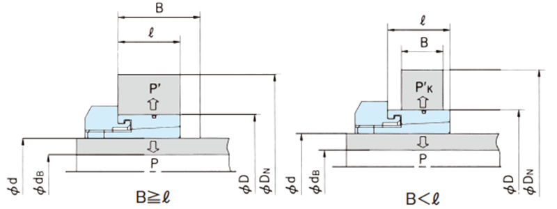
σ0.2B ≧ 1.4 × P'(B ≧ ℓの場合)
σ0.2B ≧ 1.4 × P'K(B < ℓの場合)
B < ℓの場合の面圧P'Kは次式より算出してください。
P'K = P'・ ℓ B
- P :軸側面圧 MPa{kgf/mm2}
- P'、P'k:ボス側面圧 MPa{kgf/mm2}
- σ 0.2S:使用軸材料の降伏点応力 MPa{kgf/mm2}
- σ 0.2B:使用ボス材料の降伏点応力 MPa{kgf/mm2}
鉄鋼材料の強度一覧表には、代表的な鉄鋼材料の降伏点の値を示していますので、参照ください。
(2) ボス外径の検討
使用パワーロックサイズ、使用ボス材料、ボス側面圧の値が決まりましたら、MLシリーズの主要諸元ページより、最小必要ボス外径DNを求めてください。
DN ≦ ボス径設計値
計算による場合には、次式よりDNの値を算出してください。
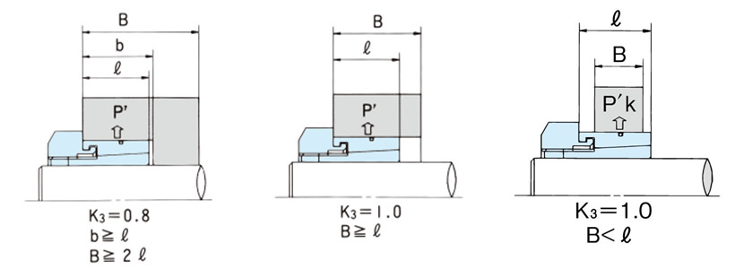
DN ≧ D σ0.2B + K3・P' σ0.2B - K3・P' (B ≧ ℓの場合)
DN ≧ D σ0.2B + K3・P'K σ0.2B - K3・P'K (B < ℓの場合)
- DN:ボス外径 mm
- D :ボス内径 mm
- σ 0.2B:ボス材料の降伏点 MPa応力 {kgf/mm2}
- P'、P'K:ボス側面圧 MPa{kgf/mm2}
- K3:ボス形状による係数(下図を参照ください。)
(3) 中空軸内径の検討
中空軸に使用される場合は、次式にて中空軸内径を算出してください。
dB ≦ d σ0.2S - 2 × P σ0.2S
- dB:最大許容中空軸内径 mm
- d:軸径 mm
- σ0.2S:軸材料の降伏点 MPa{kgf/mm2}
- P:軸側面圧 MPa{kgf/mm2}
3. ラジアル荷重
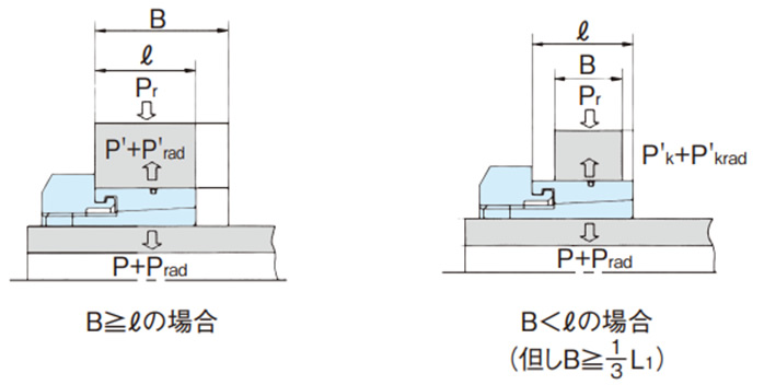
ベルト駆動などのように、大きな荷重がラジアル荷重PrとしてパワーロックMLに作用する場合、次式でラジアル荷重Prによって発生する軸側、ボス側の面圧Prad、P'rad(P'krad)を算出し、各々 Prad、P'rad(P'krad)が P、P'の25%以下であれば許容できます。
Prad = 1.3 × Pr d × ℓ ≦ 1 4 × P
P'rad = 1.3 × Pr D × ℓ ≦ 1 4 × P' (B ≧ L1の場合)
P'krad = 1.3 × Pr D × ℓ ≦ 1 4 × P'k (B < L1の場合)
- Pr:ラジアル荷重 N{kgf}
- ℓ:ボスとアウタリングの接触面幅 mm
- B:ボスの幅 mm
- d:軸径 mm
- D:ボス内径 mm
- P:軸側面圧 MPa{kgf/mm2}
- P'、P'k:ボス側面圧 MPa{kgf/mm2}
このようなラジアル荷重が作用する時のボス必要外径DNあるいは中空軸必要内径dBを求める場合は、それぞれP、P'(P'k)にPrad、P'rad を加えて算出してください。
