技術資料 パワーロック 選定と手順
選定手順や注意事項等をご覧になりたい方は下記へお進みください。
製品シリーズの絞り込みや仮選定をご希望の方は
こちらをクリックしてください。
使用条件が決まっており詳細な選定をご希望の方は
こちらをクリックしてください。
ELシリーズの選定
1. 最大発生トルクと最大発生スラスト荷重の確認
発生する伝達容量に使用係数を見込んで、最大発生トルクと最大発生スラスト荷重を求めます。
※サーボモータ・ステッピングモータの締結の場合は、それぞれの最大トルク(ピークトルク)を最大発生トルク(Tmax)としてください
| SI単位 |
|---|
|
Tmax = 9550 × H n ・f Tmax = 最大発生トルク(N・m)
|
| 重力単位 |
|---|
|
Tmax = 974 × H n ・f Tmax = 最大発生トルク(kgf・m)
|
Pmax = Pax・f
- Pmax:最大発生スラスト荷重 kN{kgf}
- Pax:スラスト荷重 kN{kgf}
- f:使用係数
f:使用係数
| 負荷の状態 | 使用係数 | |
|---|---|---|
| 衝撃のない円滑な負荷 | 慣性小 | 1.5~2.5 |
| 軽い衝撃のある負荷 | 慣性中 | 2.0~4.0 |
| 大きな衝撃のある負荷 | 慣性大 | 3.0~5.0 |
トルクのみかかる場合
以上より求められた、Tmaxとカタログ伝達トルクMtを比較します。
Mt ≧ Tmax → 使用できます。
Mt < Tmax → 形番アップあるいは複数個使用を検討ください。
トルクとスラスト荷重が同時に加わる場合
合成負荷MRを算出し、伝達トルクMtと比較します。
MR = Tmax2 + (Pmax × d 2 )2
- Tmax:最大発生トルク N・m{kgf・m}
- Pmax:最大発生スラスト荷重 N{kgf}
- d:軸径 m
以上より求められた、MRとカタログ伝達トルクMtを比較します。
Mt ≧ MR → 使用できます。
Mt < MR → 形番アップあるいは複数個使用を検討ください。
*本シリーズは複数個での使用が可能です。複数個使用する場合の伝達トルクは、Mtに下表の倍率を乗じてください。
| 使用個数 | 1 | 2 | 3 | 4 |
|---|---|---|---|---|
| 倍率 | 1 | 1.55 | 1.85 | 2 |
2. 有効加圧力、伝達トルク、面圧値の算定
(1)必要伝達トルク値Mtが、「形番と諸元」に示す伝達トルク値[Mt]と異なる場合。
次式により必要有効加圧力Fe、スラスト荷重Pax、面圧値P、P'を算出してください。
- C1 = Mt / [Mt] (必要伝達トルクの比率)
- Fe = C1 × [Fe] N{kgf} (有効加圧力)
- F = Fo + Fe N{kgf} (全加圧力)
- Pax = C1 × [Pax] N{kgf} (スラスト荷重)
- P = C1 × [P] MPa{kgf/mm2} (軸側面圧)
- P' = C1 × [P'] MPa{kgf/mm2} (ボス側面圧)
- Mt:必要伝達トルク値 N・m{kgf・m}
Fo、[Fe]、[Mt]、[Pax]、[P']は「形番と諸元」を参照ください。
(2)必要有効加圧力Feが「形番と諸元」に示す有効加圧力[Fe]と異なる場合。
次により、伝達トルク値Mt、スラスト荷重Pax、面圧P、P'を算出してください。
- C2 = Fe / [Fe] (必要有効加圧力の比率)
- Mt = C2 × [Mt] N・m{kgf・m} (伝達トルク)
- Pax = C2 × [Pax] N{kgf} (スラスト荷重)
- P = C2 × [P] MPa{kgf/mm2} (軸側面圧)
- P' = C2 × [P'] MPa{kgf/mm2} (ボス側面圧)
- Fe :必要有効加圧力 N{kgf}
Fo、[Fe]、[Mt]、[Pax]、[P']は「形番と諸元」を参照ください。注) 0.25 ≦ C2 ≦ 2
(3) パワーロックELを複数組シリーズに配列した場合。
次式により、伝達トルクMtz、スラスト荷重Paxz、面圧Pz、P'zを算出してください。(z:パワーロックEL配列数)
- Mtz = S・Mt1
- Paxz = S・Pax1
- Pz = P1 (軸側)
- P'z = P'1 (ボス側)
Mt1、Pax1、P'1は配列数1組時の値
| Z | S |
|---|---|
| 1 | 1 |
| 2 | 1.55 |
| 3 | 1.85 |
| 4 | 2 |
3. 軸とボスの検討
パワーロックEL自身にはセンタリング機能がありません。センタリングは軸とボス間のセンタリング用ガイド部で行ってください。
センタリング用ガイド部の長さはd/2以上が適当ですが、必要精度に応じてセンタリング用ガイド部公差を決定してください。
(1) 材料強度の検討
ボスおよび軸は次式を満足するような強度をもった材質のものをご使用ください。
σ0.2S ≧ 1.4 × P σ0.2B ≧ 1.4 × P'
- σ 0.2S、σ 0.2B:軸およびボス材料の降伏点 MPa{kgf/mm2}
- P、P':軸およびボス穴上に作用する面圧 MPa{kgf/mm2}
鉄鋼材料の強度一覧表には、代表的な鉄鋼材料の降伏点の値を示していますので、参照ください。
(2) ボス必要外径寸法DNおよび中空軸許容穴径dBの検討
ご使用になるボスは次式で算定するDN以上の外径寸法が必要です。また、中空軸をご使用になる場合には次式で算定するdB以内の穴径のものをご使用ください。
(a) ボルトをボス側に取付ける場合
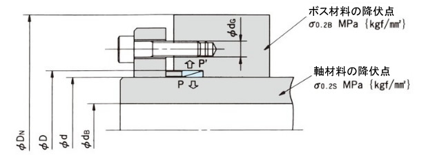
DN ≧ D σ0.2B + 0.8 × P' σ0.2B - 0.8 × P' + dG
dB ≦ d σ0.2S - 1.2 × P σ0.2S
(b) ボルトを軸側に取付ける場合
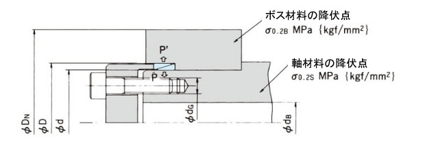
DN ≧ D σ0.2B + 0.6 × P' σ0.2B - 0.6 × P'
dB ≦ d σ0.2S - 1.6 × P σ0.2S - dG
P、P':軸側およびボス側の面圧MPa{kgf/mm2}
4. 締付ボルトの選定
(1) ボルトの強度クラスと機械的性質
ボルトの強度クラスと機械的性質はこちらを参照ください。できるだけクラス10.9、12.9のボルトの使用をおすすめします。
外部の振動に対して緩みにくい効果があります。クラス12.9ボルトを使用してクラス10.9の締付トルクで使用できます。
(2) 座面圧の検討
クラス10.9、12.9のボルトをご使用になる場合はボルト座面の面圧をご検討ください。
座面圧が次表に示す限界面圧を超えますと座面の陥没変形が時間とともに進行し、ボルトは軸力を失ってゆるみの原因となります。
座面圧が限界面圧を超える場合は、加圧フランジの機械強度をアップ(材質を変えるか熱処理を施す)するか、ボルトの締付力を小さくして座面の陥没が小さくなるようにしてください。座面面積および座面圧の計算は次式の通りです。
座面面積 = As = π 4 (D2 - da2max) mm2
- D:ボルト頭径(資料参照)mm
- da max:首下R以降円の径(資料参照)mm
- 座面圧 Ps = Fv / As MPa{kgf/mm2}
- FV:締付力 N{kgf}
各種材料の限界面圧(Junker)
| 材料 | 機械的性質 | 限界面圧 Pw MPa{kgf/mm2} |
||||||
|---|---|---|---|---|---|---|---|---|
| 名称 | ドイツ 規格 |
相当 JIS |
引張強さ MPa{kgf/mm2} |
圧縮降伏点 MPa{kgf/mm2} |
||||
| 低炭素鋼 | St37 | S10C | 346 | 35.3 | 272 | 27.9 | 294 | 30 |
| 中炭素鋼 | St50 | S30C | 505 | 51.5 | 329 | 33.6 | 490 | 50 |
| 熱処理炭素鋼 | C45 | S45C (調質) |
721 | 73.6 | 478 | 48.8 | 882 | 90 |
| 鋳鉄 | GG22 | - | 228 | 23.3 | 443 | 45.2 | 980 | 100 |
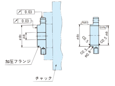
5. 加圧機構の設計
加圧フランジにはボルト締付時に大きな応力がかかりますので、塑性変形が生じないよう充分な強度をもった材料を使用し、余裕のある設計を行なってください。
以下、当社が推奨する加圧機構の設計計算式を示しますのでご参照ください。
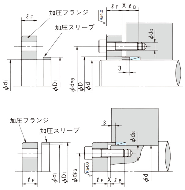
d1、D1、X寸法は下表に示していますので参照ください。
形番 d X D mm |
ギャップ X パワーロックEL 配列数 |
加圧スリーブ・ 加圧フランジ寸度 |
||||
|---|---|---|---|---|---|---|
| 1 | 2 | 3 | 4 | d1 | D1 | |
| PL010X013E | 2 | 2 | 3 | 3 | 10.1 | 12.9 |
| PL011X014E | 2 | 2 | 3 | 3 | 11.1 | 13.9 |
| PL012X015E | 2 | 2 | 3 | 3 | 12.1 | 14.9 |
| PL013X016E | 2 | 2 | 3 | 3 | 13.1 | 15.9 |
| PL014X018E | 3 | 3 | 4 | 5 | 14.1 | 17.9 |
| PL015X019E | 3 | 3 | 4 | 5 | 15.1 | 18.9 |
| PL016X020E | 3 | 3 | 4 | 5 | 16.1 | 19.9 |
| PL017X021E | 3 | 3 | 4 | 5 | 17.1 | 20.9 |
| PL018X022E | 3 | 3 | 4 | 5 | 18.1 | 21.9 |
| PL019X024E | 3 | 3 | 4 | 5 | 19.2 | 23.8 |
| PL020X025E | 3 | 3 | 4 | 5 | 20.2 | 24.8 |
| PL022X026E | 3 | 3 | 4 | 5 | 22.2 | 25.8 |
| PL024X028E | 3 | 3 | 4 | 5 | 24.2 | 27.8 |
| PL025X030E | 3 | 3 | 4 | 5 | 25.2 | 29.8 |
| PL028X032E | 3 | 3 | 4 | 5 | 28.2 | 31.8 |
| PL030X035E | 3 | 3 | 4 | 5 | 30.2 | 34.8 |
| PL032X036E | 3 | 3 | 4 | 5 | 32.2 | 35.8 |
| PL035X040E | 3 | 3 | 4 | 5 | 35.2 | 39.8 |
| PL036X042E | 3 | 3 | 4 | 5 | 36.2 | 41.8 |
| PL038X044E | 3 | 3 | 4 | 5 | 38.2 | 43.8 |
| PL040X045E | 3 | 4 | 5 | 6 | 40.2 | 44.8 |
| PL042X048E | 3 | 4 | 5 | 6 | 42.2 | 47.8 |
| PL045X052E | 3 | 4 | 5 | 6 | 45.2 | 51.8 |
| PL048X055E | 3 | 4 | 5 | 6 | 48.2 | 54.8 |
| PL050X057E | 3 | 4 | 5 | 6 | 50.2 | 56.8 |
| PL055X062E | 3 | 4 | 5 | 6 | 55.2 | 61.8 |
| PL056X064E | 3 | 4 | 5 | 7 | 56.2 | 63.8 |
| PL060X068E | 3 | 4 | 5 | 7 | 60.2 | 67.8 |
| PL063X071E | 3 | 4 | 5 | 7 | 63.2 | 70.8 |
| PL065X073E | 3 | 4 | 5 | 7 | 65.2 | 72.8 |
| PL070X079E | 3 | 5 | 6 | 7 | 70.3 | 78.7 |
| PL071X080E | 3 | 5 | 6 | 7 | 71.3 | 79.7 |
| PL075X084E | 3 | 5 | 6 | 7 | 75.3 | 83.7 |
| PL080X091E | 4 | 5 | 6 | 8 | 80.3 | 90.7 |
| PL085X096E | 4 | 5 | 6 | 8 | 85.3 | 95.7 |
| PL090X101E | 4 | 5 | 6 | 8 | 90.3 | 100.7 |
| PL095X106E | 4 | 5 | 6 | 8 | 95.3 | 105.7 |
| PL100X114E | 4 | 6 | 7 | 9 | 100.3 | 113.7 |
| PL110X124E | 4 | 6 | 7 | 9 | 110.3 | 123.7 |
| PL120X134E | 4 | 6 | 7 | 9 | 120.3 | 133.7 |
| PL130X148E | 5 | 7 | 9 | 11 | 130.4 | 147.6 |
| PL140X158E | 5 | 7 | 9 | 11 | 140.4 | 157.6 |
| PL150X168E | 5 | 7 | 9 | 11 | 150.4 | 167.6 |
(1) ボルトピッチサークル径 dpB、dpS mm
- (d = Φ10 ~ Φ30の場合) dpB = D + 8 + dG dpS = d - 8 - dG
- (d = Φ32 ~ Φ150の場合) dpB = D + 10 + dG dpS = d - 10 - dG
ただし、加圧フランジをボス側に取付ける場合、ボルト本数はdpB円周上へ取り付け可能な最大本数の1/2以下にしてください。
(2) 加圧フランジの厚さℓFmm
ℓF ≧ 2 × dG
(3) 加圧フランジの強度(σ 0.2F)
- クラス8.8のトルクでボルトを締付ける場合... σ0.2F ≧ 294 MPa{30kgf/mm2} (S35C相当)
- クラス10.9のトルクでボルトを締付ける場合... σ0.2F ≧ 343 MPa{35kgf/mm2} (S45C相当)
- クラス12.9のトルクでボルトを締付ける場合... σ0.2F ≧ 392 MPa{40kgf/mm2} (S55C相当)
σ0.2F:加圧フランジの降伏点 MPa{kgf/mm2}
(4) ねじ部はめ合い長さℓBmm
ℓB ≧ 1.5 × dG
加圧フランジ加工例
X:加圧フランジとボス端あるいは軸端の間のリング加圧時に必要な最小シメシロで表にはパワーロックEL配列数に応じた値を示しています。