技術資料 機械式過負荷保護機器 取扱
ショックガード TGX 取扱
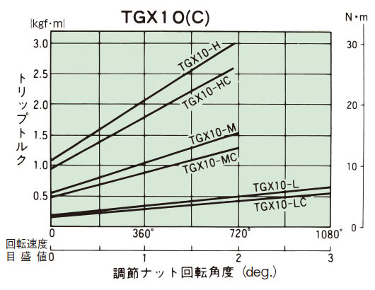
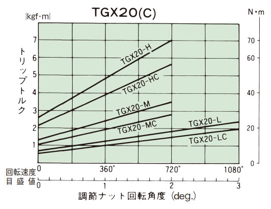
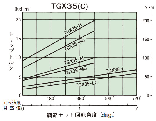
1. トリップトルクの設定
- (1)ショックガードTGXは出荷時には、すべてmin.ポイント(min.トルク値)にトルク設定をしています。インジケータが、トルク目盛のゼロを示しているのを確認してください。
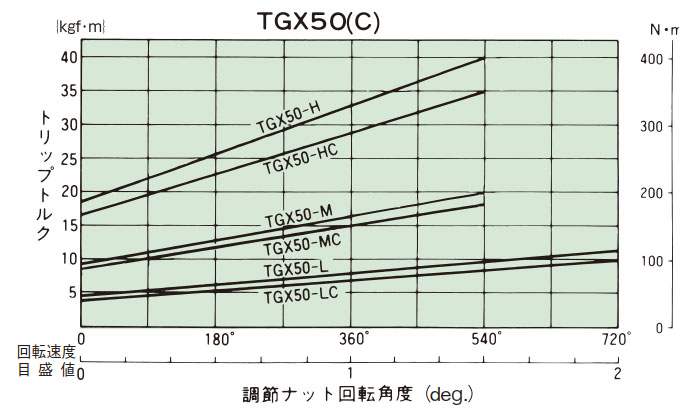
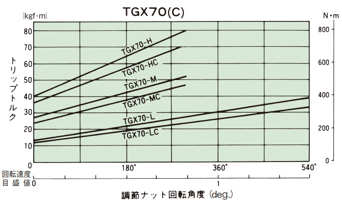
(取扱説明書をご参照ください。) - (2)締付量-トルク相関図(下表)から、あらかじめ決定されたトリップトルクに相当する調節ナット(ボルト)の締付角度を読み取り締込んでください。トルク目盛の一目盛は60°になっています。初めは、相関図から読み取った締付値の60°程手前にセットし、機械に取付けて、トリップテストを行い、順次増諦めをして、最適のトリップトルクに設定してください。製品のトリップトルクは下表の締付量-トルク相関図とは必ずしも一致しませんので目安としてご使用ください。
- (3)トルク設定が終れば調節ナットにロックスクリューを締込んでゆるみ止めとしてください。
- (4)調節ナット(ボルト)はトルク目盛の最大値以上は回さないでください。トリップ時に皿バネたわみの余裕がなくなりロック状態となります。ロックスクリューの締付トルクと注意点についてはこちらを参照してください。
締付量-トルク相関図
2. 心出し方法
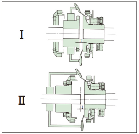
- (1)心出し方法I
- a. フランジをボスおよびセンタフランジから切り離す。
- b. 移動させる。I寸法の測定をする。(表1)
- c. 軸上にダイヤルゲージを固定し、ハブの側面と外周にて振れを測定する。
- (2)心出し方法II
- a. フランジとセンターフランジを切り離す。
- b. 軸上にダイヤルゲージを固定し、ハブの側面と外周にて振れを測定する。
- c. ボスを移動させる。I寸法の測定をする。(表1)
| 注意 | 必ず表1のI寸法で取付けてください。ノンバックラッシでの使用ができない場合があります。 |
表1
| 形番 | I寸法 mm |
|---|---|
| TGX10-C | 2 |
| TGX20-C | 3 |
| TGX35-C | 3 |
| TGX50-C | 4 |
| TGX70-C | 4 |
許容ミスアライメント量
| 形番 | 許容ミスアライメント | ||
|---|---|---|---|
| 偏角 deg. | 偏心 mm | エンドプレイ mm | |
| TGX10-C | 0.6 | 0.1 | ±0.5 |
| TGX20-C | 0.6 | 0.1 | ±0.5 |
| TGX35-C | 0.6 | 0.1 | ±0.5 |
| TGX50-C | 0.6 | 0.1 | ±0.6 |
| TGX70-C | 0.6 | 0.1 | ±0.7 |
参考 角度誤差θ = 0.1°当たりのハブ側面振れ値
| 形番 | 外径 mm | ハブの振れ値 mm |
|---|---|---|
| TGX10-C | Φ53 | 0.092 |
| TGX20-C | Φ75 | 0.131 |
| TGX35-C | Φ98 | 0.171 |
| TGX50-C | Φ138 | 0.241 |
| TGX70-C | Φ177 | 0.309 |
※角度誤差はできるだけ小さくなるよう取付けてください。
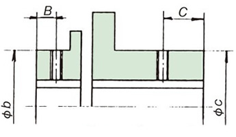
3. 軸穴加工
ショックガードTGX、カップリングタイプTGX-Cの軸穴加工時の分解、加工、組立については取扱説明書をご参照ください。
| 形番 | 寸法 | |||||
|---|---|---|---|---|---|---|
| A×ネジ径 | B×ネジ径 | C×ネジ径 | a mm | b mm | c mm | |
| TGX10 | 21×M4 以下 | - | - | 30 | - | - |
| TGX20 | 20.5×M5 以下 | - | - | 40 | - | - |
| TGX35 | 20.5×M6 | - | - | 55 | - | - |
| TGX50 | 24.5×M6 | - | - | 80 | - | - |
| TGX70 | 25×M6 | - | - | 100 | - | - |
| TGX10-C | - | 8×M4 以下 | 21×M4 以下 | - | 33 | 30 |
| TGX20-C | - | 12×M8 以下 | 20.5×M5 | - | 55 | 40 |
| TGX35-C | - | 11×M10 以下 | 20.5×M6 | - | 70 | 55 |
| TGX50-C | - | 13×M10 以下 | 24.5×M6 | - | 92 | 80 |
| TGX70-C | - | 15×M10 以下 | 25×M6 | - | 116 | 100 |
ショックガード
カップリングタイプ
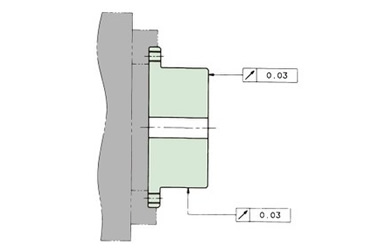
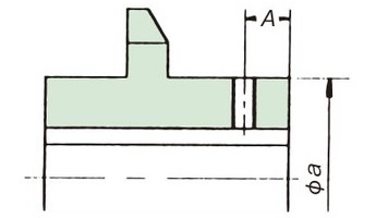
ボス端面をチャッキングし下図のように心出しを行って加工を行ってください。
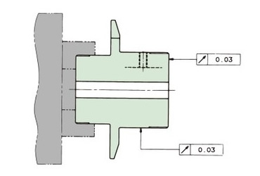
フランジ外径をチャッキングし下図のように心出しを行って加工を行ってください。