技術資料 機械式過負荷保護機器 取扱
ショックガード TGM 取扱
トルク設定
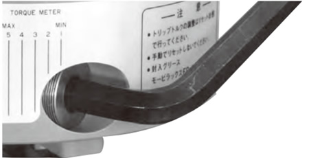
六角スパナで調整ネジを回すだけでトリップトルク精度の高いトルク設定が簡単にできます。
- 1. 出荷時はmin.トルク値に仮設定してお納めしています。調整ネジの上端面が銘板のmin.トルク(トルク目盛1)に合わせてあります。ここが締込み量の基準となります。
- 2. トルク設定の前に調整ネジのネジ部の露出面にロックタイト243または相当品を塗布してください。トルク設定後のゆるみ止めとなります。
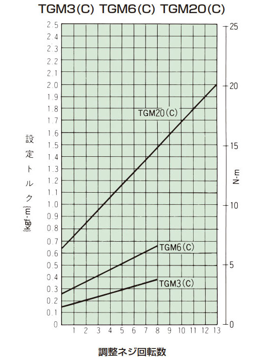
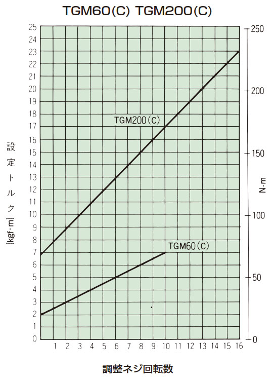
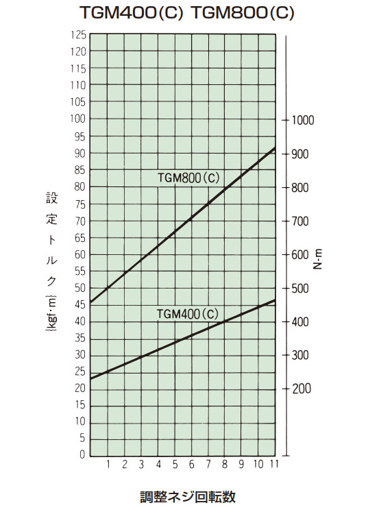
- 3. 締付量-トルク相関図または右表から、あらかじめ決定されたトリップトルクに相当する調節ナットの締付け角度を読みとり締込んでください。初めは相関図から読みとった締付け値の60°程手前にセットし、機械に取付けてトリップテストをおこない、順次増締めをして最適のトリップトルクに設定してください。製品のトリップトルクは下表の締付量-トルク相関図とは必ずしも一致しませんので目安としてご使用ください。
- 4. min.トルク(銘板のトルク目盛1)より低いトルクの設定はしないでください。min.トルクより低いトリップトルクが必要な場合には弱バネ仕様にしてください。
- 5. トリップ状態で調整ネジを回さないでください。
- 6. トルク設定のご指示がある時は工場にてトルク設定をして出荷することができます。 (取扱説明書をご参照ください。)
| 形番 | 1回転当たりのトルク変化量 N・m{kgf・m} |
総回転数 |
|---|---|---|
| TGM3 | 0.28 {0.029} | 8 |
| TGM6 | 0.48 {0.049} | 8 |
| TGM20 | 1.02 {0.10} | 13 |
| TGM60 | 4.90 {0.5} | 10 |
| TGM200 | 9.80 {1.0} | 16 |
| TGM400 | 20.6 {2.1} | 11 |
| TGM800 | 41.2 {4.2} | 11 |
設定トルク = min.トルク + (1回転当たりのトルク変化量 × 調整ネジ回転数)
締付量-トルク相関図
過負荷検出
過負荷の検出はリミットスイッチにより簡単にできます。
ショックガードが過負荷によりトリップするとカムフォロアとポケットの噛合いがはずれて、カム軸と本体(ケース)は空転します。
それにともない、ケース側面のLS検出板が軸方向にスライドします。
この動きをリミットスイッチで検出して、電源を切ったり、警報を出したりすることができます。
カム軸側、本体(ケース)側のどちらが停止側になってもこの検出はできます。
1回のトリップにLS検出板のスライドは3回あります。
- (1)表1はLS検出板の移動量、および移動時の力を示します。この表で、PT(動作までの動き)とOF(動作に必要な力)を満足する適正なリミットスイッチを選定してください。
- (2)図1、2にリミットスイッチの取付例を示します。
- (3)リミットスイッチのb接点は起動ボタンの接点と並列に接続してください。
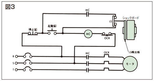
- (4)図3に代表的な回路例を示します。自己保持回路を組込んだ回路を推奨します。
| 形番 | 移動量 mm | 移動時の力 N{gf} |
|---|---|---|
| TGM3 | 4 | 3.9 {400} |
| TGM6 | 4 | 3.9 {400} |
| TGM20 | 4 | 3.9 {400} |
| TGM60 | 6 | 3.9 {400} |
| TGM200 | 6 | 5.4 {550} |
| TGM400 | 8 | 5.9 {600} |
| TGM800 | 8 | 5.9 {600} |
・リミットスイッチ取付例

・回路例
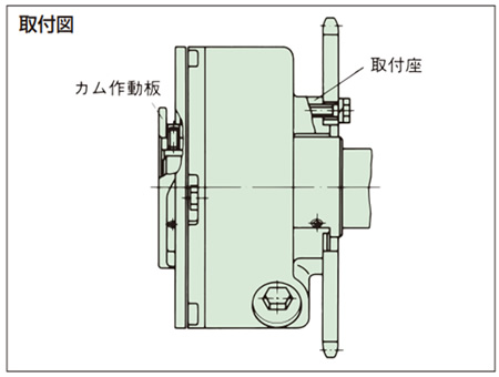
取付け
1. 軸への取付け
- ・ショックガードを軸に取付ける軸径の公差はh7を推奨します。キーはJIS 1301-1996(新JIS普通)平行キーをご使用ください。
キーを取付ける時、キーの天井をきかさないようにしてください。 - ・軸との固定はカム作動板の3ヵ所のセットボルトを利用して止めてください。(キー用×1ヵ所、軸用×2ヵ所)
- ・ショックガードを軸端に取付ける場合など、取合い関係によってカム作動板側のセットボルトが利用できない時は取付座側のタップを利用してください。
ここのタップにはセットボルトを付属しておりませんので軸穴径にあった長さのものをご用意ください。
セットボルトの頭がカム軸外周から出ないようご注意ください。頭が出たままになっていると、ショックガードがトリップした時に取付座の内径部や側面と干渉することがあります。 - ・運転中の振動などでセットボルトがゆるむおそれのある場合は、ロックタイト243または相当品を塗布してゆるみ止めとしてください。
2. ドライブメンバの取付け
- ・スプロケット、プーリ、ギヤやカップリングなどのドライブメンバの取付は3ヵ所の取付座を利用して表2の締付トルクで止めてください。
- ・スプロケットを取付ける場合は取扱説明書をご参照ください。パワーロック(締結要素)やノンバックラッシカップリングと組合せてご使用になる場合は当社までご相談ください。
3. 取付ボルト
ケースの座へ取付けるボルトのねじ込み長さおよび締付トルクは表2の値を推奨します。
また、取付物のボルト下穴はJIS B10012級以下としてください。
| 形番 | ボルトねじ込み長さ mm | ボルト締付トルク N・m{kgf・m} | 取付物のネジ下穴 mm |
|---|---|---|---|
| TGM3 | 6~7 | 2.0~2.9 {0.2~0.3} | 4.5 |
| TGM6 | 6~7 | 2.0~2.9 {0.2~0.3} | 4.5 |
| TGM20 | 8~9 | 3.9~5.9 {0.4~0.6} | 5.5 |
| TGM60 | 9~11 | 6.9~11 {0.7~1.1} | 6.6 |
| TGM200 | 15~17 | 34~51 {3.5~5.2} | 11.0 |
| TGM400 | 18~25 | 59~89 {6.0~9.1} | 14.0 |
| TGM800 | 18~25 | 59~89 {6.0~9.1} | 14.0 |
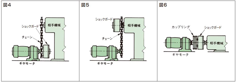
4. 連結
入・出力の連結は変・減速機、間欠駆動装置などと相手機械・装置との間で行います。
図4、5、6に代表的な連結例を示します。
再復帰
自動復帰方式ですからモータなどの駆動側を再起動するだけで自動的にリセットします。
- 1. オーバロードによりショックガードがトリップした時はいったん回転を止めて、過負荷の原因を取除いてください。
- 2. 再復帰の際は、入力回転速度50r/min.以下またはモータのインチングによりリセット(再噛合い)してください。
ショックガード本体や軸などを手で回してリセットすることは避けてください。 - 3. カムフォロアがポケットに納まる時には"カチン"と音がします。
潤滑
出荷時に高級グリースを封入していますのでそのままご使用できます。通常のご使用では給脂は不要です。
| エクソンモービル・ジャパン(同) | モービラックス EP-2 |
|---|
*上表に記載の商品名はエクソンモービル・ジャパン合同会社の商標です。
