技術資料 機械式過負荷保護機器 取扱
ショックガード TGB 取扱
1. トリップトルクの設定
- (1)ショックガードTGBは出荷時には、すべてmin.ポイント(min.トルク値)にトルク設定をしています。インジケータが、トルク目盛のゼロを示しているのを確認してください。
(各サイズの図中をご参照ください。) - (2)TGB70~130は、3ヵ所の調節ボルトのゆるみ止め用六角ナットをゆるめてください。(TGB08~50はそのまま調節ナットを回すことができます。)
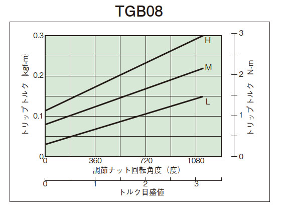
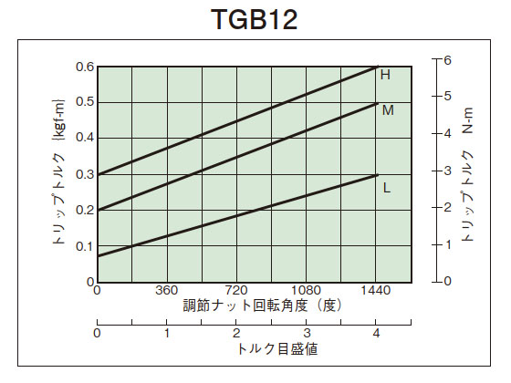
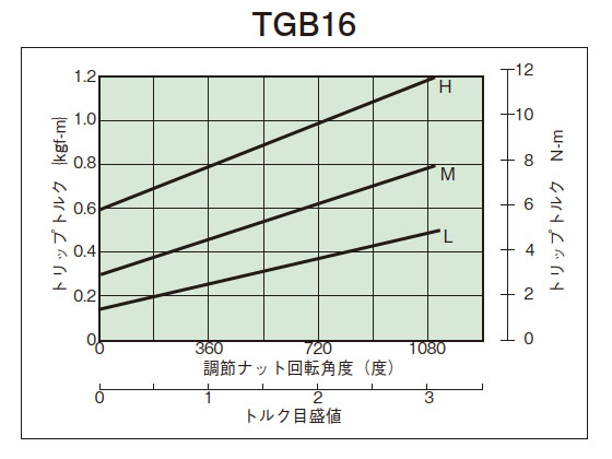
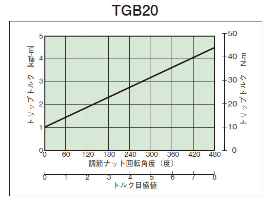
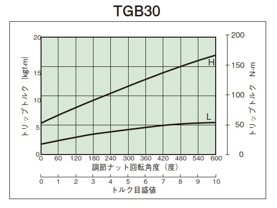
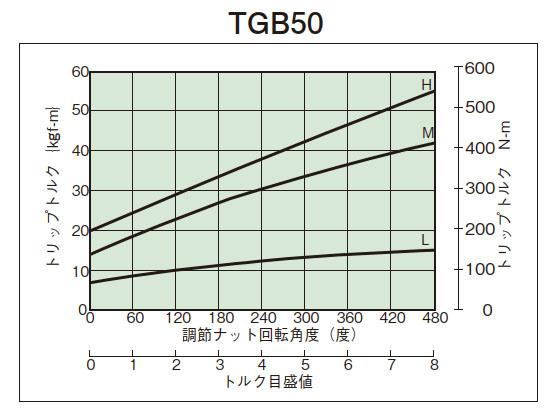
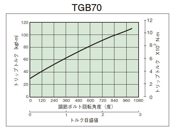
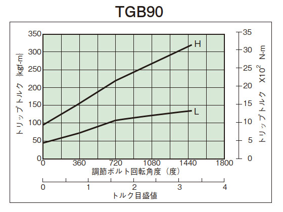
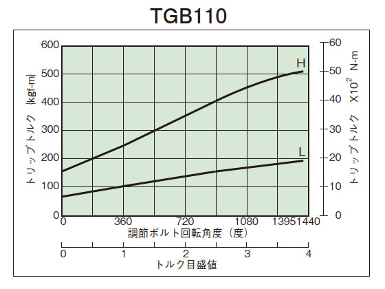
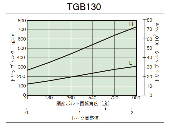
- (3)締付量-トルク相関図(下図)から、あらかじめ決定されたトリップトルクに相当する調節ナット(ボルト)の締付角度を読み取り締込んでください。初めは、相関図から読み取った締付値の60°程手前にセットし、機械に取付けてトリップテストを行い、順次増締めを行い、最適のトリップトルクに設定してください。製品のトリップトルクは下の締付量-トルク相関図と必ずしも一致しませんので目安としてご使用ください。
- (4)TGB20~50は、調節ナットはロックスクリュー1個を締込んでゆるみ止めとしてください。TGB70~130は、六角ナットを締込んでゆるみ止めとしてください。
(TGB08~16は調節ナットにコーティングを施してゆるみ止めをしています。) - (5)調節ナット(ボルト)はトルク目盛の最大値以上は回さないでください。トリップ時に皿バネたわみの余裕がなくなりロック状態となります。(TGB08~16はコイルバネです)
2. 締付量-トルク相関図
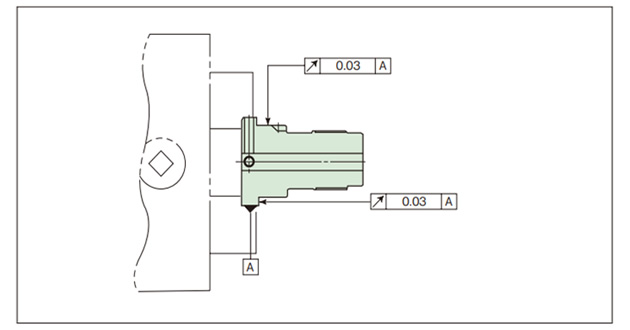
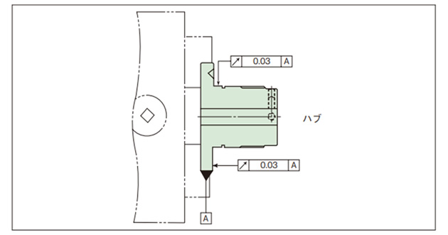
3. 軸穴加工
TGB08~16
・ボスの材質は鉄系焼結合金で表面硬化処理が施されています。
- (1)調節ナットをゆるめて全部品を分解してください。この時、各部品がチリや、ホコリで汚れないよう注意してください。
- (2)ボスのフランジ部外径をチャッキングして、ボス部で心出しをしてください。ボスの材質は鉄系焼結合金で表面硬化処理をしていますので切削用バイトには超硬材(JIS記号9-20、K-01)のご使用をお奨めします。
- (3)キー溝加工は止ネジ用タップの真下に施してください。
- (4)軸穴加工後再組立の際、ドライブボールとスラストベアリングに潤滑用のグリースを塗ってください。
- (5)軸穴加工は、下表および下図を参照の上、段付加工を行ってください。
| 形番 | 軸穴径 Φd mm |
軸穴加工長さ L mm |
座グリ径 ΦD mm |
|---|---|---|---|
| TGB08 TGB08-C |
Φ6以上 Φ8以下 | 20 | Φ11 |
| TGB12 TGB12-C |
Φ7 以上 Φ10 未満 | 20 | Φ15 |
| Φ10 以上 Φ12 未満 | 30 | ||
| Φ12 | 全長 | 不要 | |
| TGB16 TGB16-C |
Φ8 以上 Φ10 未満 | 20 | Φ15 |
| Φ10 以上 Φ12 未満 | 30 | ||
| Φ12 以上 Φ16 以下 | 全長 | 不要 |
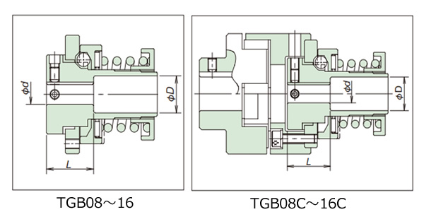
TGB20~130
・ボスは調質処理が施されています。
- (1)調節ナットをゆるめて全部品を分解してください。
ジクトメワをはずしセンタプレートもとってください。この時、各部品がチリや、ホコリで汚れないよう注意してください。 - (2)ボスのフランジ部外径をチャッキングして、ボス部で心出しをしてください。
- (3)止ネジ用のタップ加工はキー溝上と90°位置の2ヵ所に加工してください。
- (4)軸穴加工後再組立の際、ドライブボールとスラストベアリングに潤滑用のグリースを塗ってください。
4. 再復帰
自動復帰方式ですからモータなどの駆動側を再起動するだけで自動的にリセットします。
- (1)オーバロードによりショックガードがトリップした時はいったん回転を止めて、過負荷の原因を取除いてください。
- (2)再復帰の際は、入力回転速度50r/min以下またはモータのインチングによりリセット(再噛合い)してください。
⚠ショックガード本体や軸などを手で回してリセットすることは危険ですから避けてください。
- (3)ドライブボールがポケットに納まる時には"カチン"と音がします。
