技術資料 機械式過負荷保護機器 取扱
トルクキーパー TFK 取扱
取扱1
- 1. トルクキーパーはすべて下穴で出荷されます。ボスの軸穴加工は分解後に行ってください。軸穴加工についてはこちらをご参照ください。
- 2. 2個以上のトルクキーパーを分解する場合は、部品が入替わらないようにご注意ください。組立時は必ず出荷時と同じ部品で組立ててください。部品が入替わると付属のトルクカーブと実際のスリップトルクが一致しなくなります。
- 3. 歯付ベルト、ローラチェーンなどの巻掛伝動で使用する場合は、それらを張り過ぎないようにご注意ください。必要以上にテンションが作用すると安定したスリップトルクが得られないことがあります。
取扱2
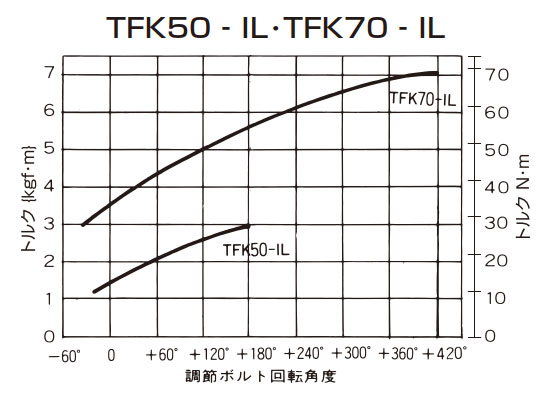
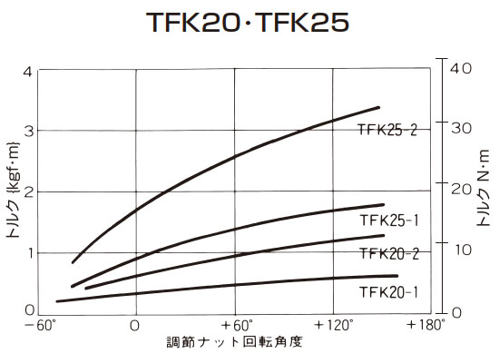
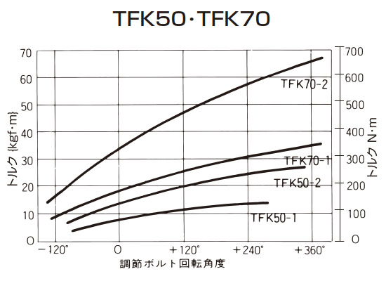
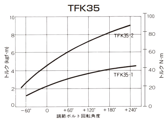
トルクキーパーは各形番とも設定トルク範囲(製品ページ参照)の最大50%の値でトルク設定を行い、そのトルクカーブを添付して出荷しています。
この50%トルクを0ポイントといい、スリップトルクの設定は、この0ポイントを基準にして行います。
TFK20・25・35のスリップトルクの設定は市販の引掛スパナで調節ナットを締付けて行ってください。TFK50・70のスリップトルクの設定は市販のスパナなどで3本の調節ボルトを締付けて行ってください。0ポイントの再現方法は下記をご参照ください。
スリップトルクの設定
TFK20・25・35
- (1)必要とするスリップトルクが0ポイント以上のときは、本体付属のトルクカーブにしたがって調節ナットを必要な角度分だけ増締めしてください。調節ナットの増締めはトルク目盛(角度表示)と合マークにより簡単にできます。
- (2)必要とするスリップトルクが0ポイント以下のときは、本体付属のトルクカーブにしたがって調節ナットを必要な角度以上にゆるめた後に、必要角度まで増締めしてください。
(例)0ポイントから-30°のスリップトルクに設定する場合。
- 1.調節ナットを0ポイントから-60°までゆるめます。
- 2.調節ナットを-60°から-30°まで増締めします。
TFK20・25・35 トルク目盛

TFK50・70
- (1)必要とするスリップトルクが0ポイント以上のときは、本体付属のトルクカーブにしたがって3本の調節ボルトを必要な角度分だけ増締めしてください。調節ボルトの増締めはトルク目盛(角度表示)と合マークにより簡単にできます。
- (2)必要とするスリップトルクが0ポイント以下のときは、本体付属のトルクカーブにしたがって3本の調節ボルトを必要な角度以上にゆるめた後に、必要角度まで増締めしてください。
(例)0ポイントから-60°のスリップトルクに設定する場合。
- 1.調節ボルトを0ポイントから-90°までゆるめます。
- 2.調節ボルトを-90°から-60°まで増締めします。
TFK50・70 トルク目盛

(注)トルクキーパーを初期設定するときや、使用途中でスリップトルクの設定値を変更する場合はより安定したスリップトルクを得るために、本運転に入る前に2~3分間のならし運転の実施をお奨めします。ならし運転は設定されるスリップトルクにより、下記の要領で行います。
(1)0ポイント以下のスリップトルクで使用される場合。
- 1. 0ポイントトルクで2~3分間のならし運転を行います。
- 2. 前述の要領でスリップトルクの設定を行ってから本運転に入ってください。
(2)0ポイント以上のスリップトルクで使用される場合。
- 1. 前述の要領でスリップトルクの設定を行います。
- 2. 2~3分間のならし運転を行います。
- 3. 調節ナットまたは調節ボルトを0ポイントにもどします。
- 4. 再度、スリップトルクの設定を行ってから本運転に入ってください。
トルクカーブ (カップリングタイプも共通)
弱バネ仕様

標準バネ仕様 { }は参考値です。
0ポイントの再現方法
軸穴加工後の再組立時に下記の要領で行ってください。
TFK20・25・35
- 1. 再組立時にトルク目盛0はボスの穴付止ネジ(こちらの品番(8))の位置に合わせて組込んでください。 (180°逆にならないようにご注意ください。)
- 2. 調節ナットを手で締付け、さらに引掛スパナで調節ナットの合マークがトルク目盛の0の位置にくるまで締付けてください。
TFK50・70
- 1. 調節ナットを締付け、調節ナットとボスの合マークを合わせてください。
- 2. 調節ボルトを手で締付け、さらにスパナ、モンキレンチなどで、トルク目盛の0が合マークの位置にくるまで締付けてください。
- 注)1. トルクカーブの目盛0は最大トルクの50%の値を示しています。
- 注)2. 各トルクカーブは代表例です。実際のご使用に当たっては、本体付属のトルクカーブをご参照ください。
