技術資料 カップリング 取扱
エクトフレックスカップリング NEF・NEHシリーズ 取扱
心出し
(1) シングルタイプ、スペーサタイプ
カップリングの最初の心出し精度が高ければ高い程、使用中に発生する偏心回転応力を抑えることができます。
軸受の摩耗、据付面の沈下、温度による状態変化、振動などによる使用中の変化が、お客様の機器とカップリングの寿命を短くすることになります。
定期的に以下の手順にしたがって調整を行ってください。

偏心(平行誤差) = L×tan 1/2 θa L:ディスクの中心間距離 = J - E
シングルタイプは偏心(軸心の平行ズレ)を吸収できませんので、ご注意ください。
カップリングの許容偏角(角度誤差)、偏心(平行誤差)、フランジ面間寸法誤差は相関関係にあり、一方が増加すると一方が減ずるため同時に考慮する必要があります。下記の推奨値以下に最初の心出しを確実に行ってください。
| 形番 | 偏角(角度誤差) | 偏心 (平行誤差) ε[mm] |
ハブ面間 寸法誤差 E[mm] |
|
|---|---|---|---|---|
| 1/2 θ a [deg] |
ダイヤル読み値 | |||
| NEF02S | 0.25 | 0.25 | ※(注) 吸収できません |
4.9±0.25 |
| NEF04S | 0.25 | 0.29 | 6.1±0.25 | |
| NEF10S | 0.25 | 0.35 | 6.6±0.25 | |
| NEF18S | 0.25 | 0.40 | 8.3±0.25 | |
| NEF25S | 0.25 | 0.45 | 11.2±0.25 | |
| NEF45S | 0.25 | 0.55 | 11.7±0.25 | |
| NEF80S | 0.25 | 0.62 | 11.7±0.25 | |
| NEF130S | 0.25 | 0.73 | 16.8±0.25 | |
| NEF210S | 0.25 | 0.84 | 17.0±0.25 | |
| NEF340S | 0.25 | 0.93 | 21.6±0.25 | |
| NEF540S | 0.25 | 1.07 | 23.9±0.25 | |
| NEF700S | 0.25 | 1.20 | 27.2±0.25 | |
※注) シングルタイプは構造上偏心(角度誤差)を吸収できませんが、心出しの際は0.02mm以内で調整してください。
| 形番 | 偏角(角度誤差) | 偏心 (平行誤差) ε[mm] |
ハブ面間 寸法誤差 E[mm] |
|
|---|---|---|---|---|
| θ a [deg] |
ダイヤル読み値 T.I.R.[mm] |
|||
| NEF02W | 0.5 | 0.50 | 0.075 | 4.9±0.25 |
| NEF04W | 0.5 | 0.58 | 0.13 | 6.1±0.25 |
| NEF10W | 0.5 | 0.71 | 0.14 | 6.6±0.25 |
| NEF18W | 0.5 | 0.81 | 0.17 | 8.3±0.25 |
| NEF25W | 0.5 | 0.91 | 0.18 | 11.2±0.25 |
| NEF45W | 0.5 | 1.10 | 0.22 | 11.7±0.25 |
| NEF80W | 0.5 | 1.25 | 0.25 | 11.7±0.25 |
| NEF130W | 0.5 | 1.46 | 0.27 | 16.8±0.25 |
| NEF210W | 0.5 | 1.69 | 0.31 | 17.0±0.25 |
| NEF340W | 0.5 | 1.86 | 0.33 | 21.6±0.25 |
| NEF540W | 0.5 | 2.14 | 0.37 | 23.9±0.25 |
| NEF700W | 0.5 | 2.41 | 0.46 | 27.2±0.25 |
| NEH09W | 0.35 | 1.68 | 0.30 | 19.0±0.25 |
| NEH14W | 0.25 | 1.20 | 0.30 | 19.0±0.25 |
| NEH20W | 0.25 | 1.34 | 0.33 | 19.0±0.25 |
| NEH30W | 0.25 | 1.50 | 0.36 | 21.5±0.25 |
| NEH41W | 0.25 | 1.64 | 0.43 | 24.0±0.25 |
| NEH55W | 0.25 | 1.94 | 0.50 | 29.5±0.25 |
| NEH70W | 0.25 | 2.05 | 0.51 | 31.3±0.25 |
| NEH90W | 0.25 | 2.23 | 0.55 | 32.0±0.25 |
| NEH110W | 0.25 | 2.43 | 0.55 | 32.5±0.25 |
| NEH135W | 0.25 | 2.56 | 0.60 | 34.0±0.25 |
| NEH150W | 0.25 | 2.74 | 0.65 | 34.5±0.25 |
| NEH180W | 0.25 | 2.85 | 0.70 | 35.5±0.25 |
(2) ロングスペーサタイプ

| 形番 | 偏角(角度誤差) | 偏心 (平行誤差) ε[mm] |
ハブ面間 寸法誤差 E[mm] |
|
|---|---|---|---|---|
| θ a [deg] |
ダイヤル読み値 T.I.R.[mm] |
|||
| NEF04W | 0.5 | 0.58 | L×0.43×10⁻² | 6.1±0.25 |
| NEF10W | 0.5 | 0.71 | L×0.43×10⁻² | 6.6±0.25 |
| NEF18W | 0.5 | 0.81 | L×0.43×10⁻² | 8.3±0.25 |
| NEF25W | 0.5 | 0.91 | L×0.43×10⁻² | 11.2±0.25 |
| NEF45W | 0.5 | 1.10 | L×0.43×10⁻² | 11.7±0.25 |
| NEF80W | 0.5 | 1.25 | L×0.43×10⁻² | 11.7±0.25 |
| NEF130W | 0.5 | 1.46 | L×0.43×10⁻² | 16.8±0.25 |
| NEF210W | 0.5 | 1.69 | L×0.43×10⁻² | 17.0±0.25 |
| NEF340W | 0.5 | 1.86 | L×0.43×10⁻² | 21.6±0.25 |
| NEF540W | 0.5 | 2.14 | L×0.43×10⁻² | 23.9±0.25 |
| NEF700W | 0.5 | 2.41 | L×0.43×10⁻² | 27.2±0.25 |
| NEH09W | 0.35 | 1.68 | L×0.31×10⁻² | 19.0±0.25 |
| NEH14W | 0.25 | 1.20 | L×0.22×10⁻² | 19.0±0.25 |
| NEH20W | 0.25 | 1.34 | L×0.22×10⁻² | 19.0±0.25 |
| NEH30W | 0.25 | 1.50 | L×0.22×10⁻² | 21.5±0.25 |
| NEH41W | 0.25 | 1.64 | L×0.22×10⁻² | 24.0±0.25 |
| NEH55W | 0.25 | 1.94 | L×0.22×10⁻² | 29.5±0.25 |
| NEH70W | 0.25 | 2.05 | L×0.22×10⁻² | 31.3±0.25 |
| NEH90W | 0.25 | 2.23 | L×0.22×10⁻² | 32.0±0.25 |
| NEH110W | 0.25 | 2.43 | L×0.22×10⁻² | 32.5±0.25 |
| NEH135W | 0.25 | 2.56 | L×0.22×10⁻² | 34.0±0.25 |
| NEH150W | 0.25 | 2.74 | L×0.22×10⁻² | 34.5±0.25 |
| NEH180W | 0.25 | 2.85 | L×0.22×10⁻² | 35.5±0.25 |
スペーサタイプの偏心(平行誤差)と偏角(角度誤差)の関係
偏心(平行誤差)
(ディスクの中心間距離Lの単位長さ当たりの偏心(平行誤差)量)
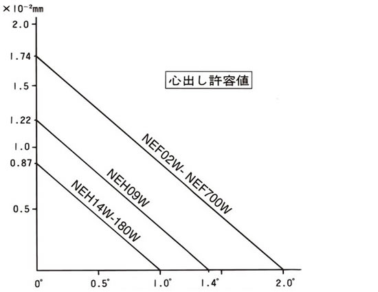
許容偏角(角度誤差)(θa)
偏心(平行誤差)
(ディスクの中心間距離Lの単位長さ当たりの偏心(平行誤差)量)
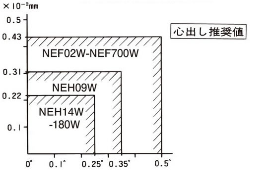
許容偏角(角度誤差)(θa)
- (1) ハブ間寸法(E)の調整
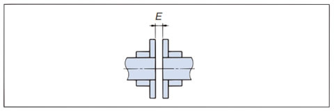
スペーサタイプ、シングルタイプともE寸法を90度毎に4ヵ所測定し、その平均値がE±0.25mm以内となるようハブの位置を調整してください。
駆動軸、被動軸が段付きシャフトの場合は、調整代が制限される場合がありますのであらかじめE寸法が調整可能なように配慮ください。
- (2) 偏角(角度誤差)(θ°)の調整

- (a) 上図のようにダイヤルゲージを片側ハブに固定し、そのハブを回転させダイヤルゲージの最小読みを見つけ、ゼロにセットしてください。
- (b) ダイヤル側のハブを360度回転させ、偏角(角度誤差)の数値を読みとってください。
- (c) ダイヤルゲージの読みが表の偏角(角度誤差)推奨値の範囲に入るように機器をシムなどで移動させて調整してください。
- (3) 偏心(平行誤差)(ε)mmの調整

- (a) 上図のようにハブフランジにダイヤルゲージを取付け、そのハブを回転させダイヤルゲージの最小読みを見つけ、ゼロにセットしてください。
- (b) ダイヤルゲージ固定側のハブを360度回転させ、偏心の数値を読みとってください。
- (c) ダイヤルゲージの外周部のフレが、ハブのキリ穴部分で、異常に振れる場合があります。これは、キリ穴部分で加工する際、フランジが外周方向にふくらんだためですので、その部分を避けて読み取ってください。
- (d) ダイヤルゲージの読みが表の偏心(平行誤差)推奨値(ε)の2倍以内の範囲に入る様に機器をシムなどで移動させて調整してください。
- (e) 偏心(平行誤差)の調整のため、機器を移動させた場合には、再度、偏角(角度誤差)の調整を行ってください。
- (4) カップリングのすべての変位が適正な値になるまで上記作業を繰返してください。
- (5) 次項の所定のトルクですべてのUナットを締付けてください。
エクトフレックスカップリングのトルクの伝達は、Uナットの締付力によるディスクとワシャ間に発生する摩擦力によって行われています。
次項のUナットの締付トルクを必ず守ってください。
1. リーマボルトの締付トルク一覧表
エクトフレックスカップリングはリーマボルト、Uナットの摩擦力によって動力伝達を行います。
規定トルクにて確実に締付けてください。
| 形番 | リーマボルト締付トルク [N・m] |
リーマボルトサイズ | |
|---|---|---|---|
| NEF02 | 4.90 | M5 | |
| NEF04 | 8.82 | M6 | |
| NEF10 | 8.82 | M6 | |
| NEF18 | 21.6 | M8 | |
| NEF25 | 21.6 | M8 | |
| NEF45 | 41.2 | M10 | |
| NEF80 | 78.4 | M12 | |
| NEF130 | 78.4 | M12 | |
| NEF210 | 177 | M16 | |
| NEF340 | 177 | M16 | |
| NEF540 | 470 | M20 | |
| NEF700 | 657 | M24 | |
| NEH09 | 470 | M20 | |
| NEH14 | 568 | M22 | |
| NEH20 | 784 | M24 | |
| NEH30 | 1170 | M27 | |
| NEH41 | 1590 | M30 | |
| NEH55 | 2250 | M36 | |
| NEH70 | 2550 | M36 | |
| NEH90 | 3230 | M39 | |
| NEH110 | 3920 | M42 | |
| NEH135 | 4900 | M45 | |
| NEH150 | 5490 | M48 | |
| NEH180 | 6860 | M52 | |
| 形番 | リーマボルトA 締付トルク [N・m] |
リーマボルトA サイズ |
リーマボルトB 締付トルク [N・m] |
リーマボルトB サイズ |
||||
|---|---|---|---|---|---|---|---|---|
| NEF45G | 41.2 | M10 | 8.82 | M6 | ||||
| NEF80G | 78.4 | M12 | 21.6 | M8 | ||||
| NEF130G | 78.4 | M12 | 21.6 | M8 | ||||
| NEF210G | 177 | M16 | 41.2 | M10 | ||||
| NEF340G | 177 | M16 | 41.2 | M10 | ||||
| NEF540G | 470 | M20 | 78.4 | M12 | ||||
| NEF700G | 657 | M24 | 78.4 | M12 | ||||
| NEH09G | 470 | M20 | 78.4 | M12 | ||||
| NEH14G | 568 | M22 | 78.4 | M12 | ||||
| NEH20G | 784 | M24 | 177 | M16 | ||||
| NEH30G | 1170 | M27 | 177 | M16 | ||||
| NEH41G | 1590 | M30 | 470 | M20 | ||||
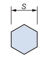
| サイズ | M5 | M6 | M8 | M10 | M12 | M16 | M20 | M22 | M24 |
|---|---|---|---|---|---|---|---|---|---|
| S | 8 | 10 | 13 | 17 | 19 | 24 | 30 | 32 | 36 |
| サイズ | M27 | M30 | M36 | M39 | M42 | M45 | M48 | M52 | |
| S | 41 | 46 | 55 | 60 | 65 | 70 | 75 | 80 |
2. リーマボルトの締付け
リーマボルトを締付ける時、カップリングハブに軸方向の力を加えると、ディスクがたわみ、そのままの状態で固定されることがありますので、リーマボルトの締付時にはハブに軸方向の力を与えないようにご注意ください。
上表の締付トルクにてしっかりと締付けてください。
- ・Uナットは金属製ですので20回までの脱着が可能です。これ以上の脱着を行う場合はUナットを補用部品としてご準備ください。
- ・リーマボルトにオイル・グリースの塗布は不要です。
- ・リーマボルトはどちらから入れても構いません。
3. カップリングの取外し
スペーサタイプのカップリングを軸から取外す際、駆動機や被動機を動かさずに行うことができるので、再取付時の心出し作業が大変容易になります。
[取外し手順]
- 1. すべてのリーマボルトをゆるめて、ディスク、スペーサを取除きます。(図1)
- 2. ハブ固定用のセットボルトをゆるめて、ハブをスライドさせ取外します。(図2)
- 3. 再組立はこの逆の手順で作業をします。両ハブを軸に取付けた際確認のため心出しレベルのチェックを推奨します。
図1

図2
4. 点検
実際の運転に入って1~2時間後に、偏角(角度誤差)と偏心(平行誤差)を再チェックしてください。その際、ボルトナットを上表の規定トルクで再締付けしてください。
半年~1年毎にリーマボルト、Uナットにゆるみがないかチェックしてください。ゆるみのチェックのために据付け後、リーマボルトとUナットへマーキングを入れておかれることを推奨します。その他の部品にも異常がないかチェックしてください。
