Technical Data  Coupling  Handling

Power Rigid Couplings  EPR Series  Handling

Mounting

Clean the shaft surfaces and body inner circumferences by wiping them off, then apply a thin coating of oil to the parts.

1. Mounting shaft tolerance

The table below shows the tolerances of shafts on which Power Rigid Couplings are mounted.

Mounting shaft diameter Φ35 Other
The recommended tolerance
+0.010
-0.010
h6 or h7

Servomotor shaft diameters of 35 mm have a tolerance of (+0.01~0 ).
The coupling bore tolerance is therefore matched to this value.
Note that both bore tolerances are the same even for ball screw shaft diameters of 35 mm.

  • ・The yield point of the mounting shaft material should be 343MPa{35kgf/mm2} or more (equivalent to S45C or more).
  • ・The surface roughness of the shaft should be Ra1.6 or less.

2. Centering

  • (1) Attach the coupling to one shaft, and fasten the outer ring as described in the product’s user manual.
  • (2) Leave the outer ring for the other shaft unfastened. This shaft is allowed to rotate freely within the coupling’s bore.
  • (3) Fasten the dial gauge to the base (such as the coupling case), and check the runout of each shaft as described below.
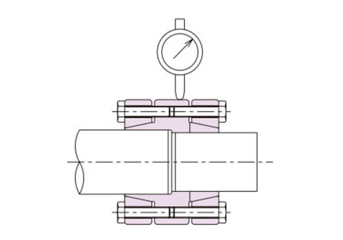
    • 1. Check the runout of the shaft with the connected coupling by placing the dial gauge against the outer circumference of the center flange in the body of the coupling. Rotate this shaft and read the runout.
      Adjust the runout to within 3/100. (Fig. 1)
    • 2. Next, place the dial gauge against the other shaft. Rotate the shaft and read the runout. Adjust the runout to within 3/100.
  • (4) Check that both runout values shown by the dial gauge are within the standard value, then fasten the second outer ring as described in the product’s user manual.
  • (5) Finally, read the runout of the body’s flanges, and check that it is within 3/100.
Recommended centering precision
Dial gauge at body outer circumference
Within 3/100mm
Fig. 1

Fig. 1

Fig. 2

Fig. 2

3. Fastening pressure bolts

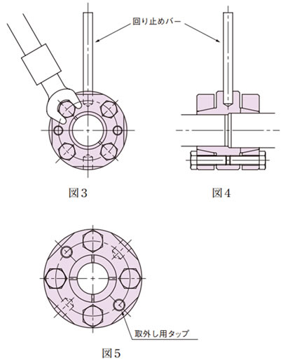
To fasten the pressure bolts, first fasten them finger-tight, then gradually tighten the diagonally opposing bolts. (Fig. 3)

Finally, use a torque wrench to tighten them to the specified tightening torque of 16.7 N·m {1.70 kgf·m}.

When tightening the pressure bolts, place the dial gauge against the body outer circumference and tighten so that the runout value shown by the gauge is as close to 0 as possible. (Fig. 2)

Inserting a locking bar into a drilled hole on the body outer circumference to hold the coupling will make the procedure easier. (Fig. 4)

4. Removal

Loosening the pressure bolts releases the Taper-Lock’s attachment. If the coupling is stuck, it can be removed by fastening pressure bolts to the outer ring’s removal taps (two). (Fig. 5)

5. Inspection

After mounting the coupling, perform trial operation and check for any abnormal vibrations, noise or other problems. Also check for any pressure bolt looseness.

6. Maintenance

Check the mounting state once or twice a year. Take immediate steps to remedy any problems discovered.
Fig. 3,4,5