技術資料 カップリング 取扱
パワーリジッドカップリング EPRシリーズ 取扱
取付
軸表面やボディ内周をきれいに拭き、各部品にオイルを薄く塗ってください。
1. 取付軸径公差
パワーリジッドカップリングを取付ける軸径の公差は、下表の通りとしてください。
| 取付軸径 | Φ35 | Φ35以外 |
|---|---|---|
| 推奨公差 | +0.010 -0.010 |
h6またはh7 |
Φ35はサーボモータの軸径で、公差が(+0.01~0)となっています。
従って、カップリングの穴公差もそれに合わせています。
ボールネジ軸径がΦ35の場合でも両方の穴径公差は同じですのでご注意ください。
- ・取付軸材の降伏点は343MPa{35kgf/mm2}以上(S45C相当以上)としてください。
- ・軸の表面粗さはRa1.6以下としてください。
2. 心出し
- (1) 片側軸にカップリングを取付け、アウタリングを手順に従い締込み固定してください。
- (2) 他方の軸はアウタリングの締込みはしないままにしてください。この軸はカップリングの軸穴内を自由に回転できる状態です。
- (3) ダイヤルゲージをベース(カップリングケース等)に固定し、各々の軸振れをチェックします。
- 1. カップリングを締結した軸は、カップリングのボディの中央フランジ外周部にダイヤルゲージをあてます。
この軸を回転させ振れを読み取り3/100以内にしてください。(図1) - 2. 次に他方の軸にダイヤルゲージをあてて、この軸を回転させ振れを読み取り3/100以内にしてください。
- 1. カップリングを締結した軸は、カップリングのボディの中央フランジ外周部にダイヤルゲージをあてます。
- (4) ダイヤルゲージの振れが共に規格値内であることを確認して、他方のアウタリングを手順通りに締込んでください。
- (5) 最後に本体のフランジの振れをダイヤルゲージで読み取り振れ3/100以内であることを確認してください。
| 本体外周部ダイヤルゲージ |
|---|
| 3/100mm以内 |

図1
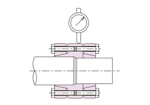
図2
3. 加圧ボルトの締付け
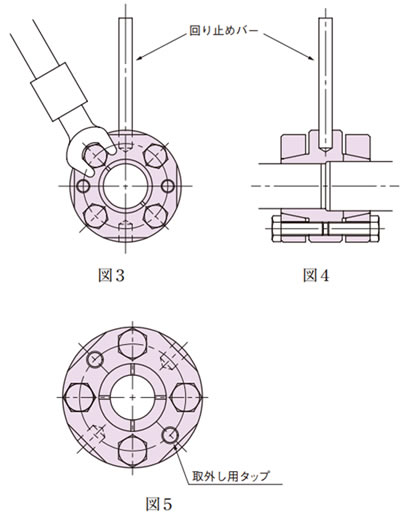
加圧ボルトの締付けは、手で予備締めをしたあと、対角のボルトを徐々に増し締めしてください。(図3)
最後は、トルクレンチを使って規定の締付トルク16.7N・m{1.70kgf・m}で締込んでください。
この時、ボディ外径部にダイヤルゲージをあて、ゲージの振れをできるだけ0に近付けるように加圧ボルトを締付けてください。(図2)
またボディ外周のキリ穴に回り止めバーを差し込んで固定していただければ作業が容易になります。(図4)
4. 取外し
加圧ボルトをゆるめるとテーパロックの締付けが解除されます。もし固着状態の場合には、アウタリングの取外し用タップ(2カ所)に加圧ボルトを締めて、外すことができます。(図5)5. 点検
取付後試運転を行い、振動、異音等の異常がないことを確認してください。また、加圧ボルトのゆるみ等がないかも確認してください。6. メンテナンス
年に1~2回、取付状態の確認をしてください。もし異常が見つかれば速やかに対処してください。