技術資料 減速機 ウォーム減速機 選定
選定手順や注意事項等をご覧になりたい方は下記へお進みください。
製品シリーズの絞り込みや仮選定をご希望の方は
こちらをクリックしてください。
使用条件が決まっており詳細な選定をご希望の方は
こちらをクリックしてください。
選定手順
まずフローチャートで選定テーブルを特定してください。
次にEWJ・EW・SWJ・SWシリーズの選定テーブル1、2に該当しない運転条件「選定テーブル3」、およびTDシリーズの場合は下記の手順で選定してください 。
選定に必要な条件は、負荷トルクまたは伝動 kW・入力回転速度・減速比・負荷の性質・使用時間・起動停止の頻度など。
1. 補正係数の決定
選定テーブル 3記載の伝動能力表は、すべて使用係数(Sf)を1.0とした場合の値です。負荷特性と運転時間・起動頻度に応じて使用係数(Sf)および熱定格係数(EWJ・EW・SWJ・SWシリーズのみ適用)を選び、どちらか大きい方を補正係数とします。また負荷の性質は、機械別負荷分類表を参照ください。機械名がない場合は、類似の機械を選ぶか当社までご相談ください。
表1使用係数表(Sf)
| 負荷の性質 | 使用時間(1日当たり) | ||
|---|---|---|---|
| 2 | 10 | 24 | |
| U:均一な荷重 | 1.00 (1.25) |
1.00 (1.25) |
1.25 (1.50) |
| M:多少衝撃の伴う荷重 | 1.00 (1.25) |
1.25 (1.50) |
1.50 (1.75) |
| H:大きな衝撃の伴う荷重 | 1.25 (1.50) |
1.50 (1.75) |
1.75 (2.00) |
注
- 1)起動回数が1時間当たり10回以上の場合は、( )内の数値を使用します。
- 2)上記使用係数表は一般的な目安です。使用条件を考慮して決定ください。
表2.熱定格係数(EWJ・EW・SWJ・SW シリーズ)
| 入力回転速度 r/min |
サイズ | 減速比 運転時間 |
熱定格係数 |
|---|---|---|---|
| 1750, 1450 | EWJ25 ~ 70 SWJ25 ~ 42 |
1/10 ~ 1/60 連続運転 1時間以上 |
1.3 |
| SWJ50 ~ 70 | 1.15 | ||
| 1750, 1450 | EW80 ~ 200 SW80 ~ 200 |
1/10 ~ 1/60 連続運転 2時間以上 |
1.5 |
| 1150, 950 | EW80 ~ 200 SW80 ~ 200 |
1.15 | |
| 上記以外の場合 | 1.0 | ||
2. 補正kW・補正トルクの決定
補正kWまたは補正トルクを式1にて決定します。
補正kW = 負荷kW × 補正係数........(式1)
補正トルク = 負荷トルク × 補正係数...(式1)
3. 減速比の決定
使用する入力回転速度と必要な出力回転速度から、減速比を決定します。入力回転速度が1750r/minを超える場合は当社までお問合せください。
4. サイズ・形番の決定
伝動能力表より補正kWまたは補正トルクを満足するサイズ・形番を選定ください。
入力回転速度が100r/min以下で使用する場合には、伝動能力表中の100r/minの出力トルクで選定ください。
なお、TDシリーズについては選定したサイズに対し、下記項目を確認ください。
[等価熱容量の確認:TDシリーズ]
ご使用の周囲温度と温度補正係数表(表3)から温度補正係数(f1)を決定し、等価熱容量を求め、各製品ページの伝動能力表の能力内かどうかを式2で確認ください。
等価熱容量 = 負荷kW(またはトルク) × f1......(式2)
表3. 温度補正係数表(f1) (TDシリーズ)
| 周囲温度 | 温度補正係数 |
|---|---|
| 30℃以下 | 1.0 |
| 40℃以下 | 1.3 |
| 50℃以下 | 1.5 |
5. 軸荷重の確認
軸に発生するラジアル荷重が、各シリーズの許容ラジアル荷重以内かどうか、式3で確認してください。
許容ラジアル荷重(N{kgf})≧ T × f × Lf R ...(式3)
- T:補正トルク(N・m {kgf・m})
- f:O.H.L.係数(下表)
- Lf:作用位置係数(下表)
- R:スプロケット、プーリ等のピッチ円半径(m)
O.H.L.係数(f)
| チェーン | 1.00 |
|---|---|
| ギヤ 歯付ベルト |
1.25 |
| Vベルト 強力歯付ベルト |
1.5 |
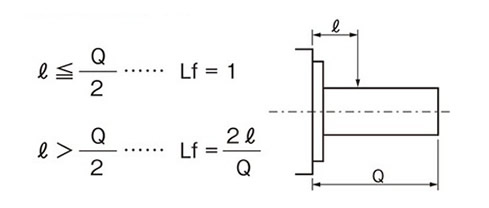
出力軸中実タイプ
作用位置係数(Lf)
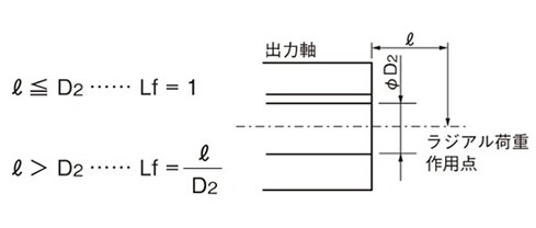
出力軸中空タイプ
作用位置係数(Lf)
アキシャル荷重の確認
出力軸にアキシャル荷重が発生する場合には、各シリーズの許容アキシャル荷重以内かどうか確認してください。
ラジアル荷重とアキシャル荷重が同時に発生する場合には、当社までお問合せください。
交番荷重について
インデックス駆動など高頻度で交番荷重が掛かる用途では減速機のバックラッシ量や締結部のガタ等から思わぬトラブルに繋がるおそれがあります。
このような用途でご検討される場合は選定仕様確認書に使用条件を記載いただき、当社までお問合せください。
6. 必要入力kWの算出
必要入力kW = 定格入力kW × 負荷トルク 定格出力トルク × Sf
