技術資料 減速機 ウォーム減速機TERUS 選定
選定手順や注意事項等をご覧になりたい方は下記へお進みください。
製品シリーズの絞り込みや仮選定をご希望の方は
こちらをクリックしてください。
使用条件が決まっており詳細な選定をご希望の方は
こちらをクリックしてください。
選定手順
TERUS EWJGM・EWGM(R)・SWJGM・SWGM(R)・TDGM(R)シリーズの場合は下記の手順で選定してください。
選定に必要な条件は、モータ容量・負荷トルク・入力回転速度・減速比・負荷の性質・使用時間・起動停止の頻度など。
1. 仕様:A・B・C・Xタイプの決定
ご使用用途に応じて、ジャストフィットな仕様を選んでください。
- Aタイプ:標準仕様
......汎用性の高い、高効率・出力重視の組合せ - Bタイプ:セルフロック仕様
......昇降装置・反転機などに適した静止状態におけるセルフロック性を重視した組合せ - Cタイプ:エコ仕様
......ごみ処理機・破砕機など衝撃荷重に考慮したギヤ強度重視の組合せ - Xタイプ:組合せ特殊
......ギヤモータ・ウォームのサイズ・速比を任意に組合せ。(別途ご相談ください。)
2. 使用係数の決定
特性表の出力軸許容トルクおよびモータkWは、すべて使用係数(sf)を1.0とした場合の値です。負荷特性と運転時間・起動頻度に応じて使用係数(sf)を選び、どちらか大きい方を補正係数とします。
また負荷の性質は、機械別負荷分類表を参照ください。機械名がない場合は、類似の機械を選ぶか当社までご相談ください。
表1使用係数表(Sf)
| 負荷の性質 | 使用時間(1日当たり) | |||
|---|---|---|---|---|
| 0.5 | 2 | 10 | 24 | |
| U:均一な荷重 | 1.00 (1.00) | 1.00 (1.00) | 1.00 (1.25) | 1.25 (1.50) |
| M:多少衝撃の伴う荷重 | 1.00 (1.00) | 1.00 (1.25) | 1.25 (1.50) | 1.50 (1.75) |
| H:大きな衝撃の伴う荷重 | 1.00 (1.25) | 1.25 (1.50) | 1.50 (1.75) | 1.75 (2.00) |
注)
- (1) 起動回数が1時間当たり10回以上の場合は、( )内の数値を使用します。
- (2) 上記使用係数表は一般的な目安です。使用条件を考慮して決定ください。
3. 補正トルクの決定
必要な負荷トルクもしくは必要なモータkWに対し、補正係数を乗じ補正トルクを式1にて決定します。
補正トルク = 負荷トルク × 補正係数 ......(式1)
補正kW = モータkW × 補正係数 ......(式1)
4. 減速比の決定
使用する入力回転速度と必要な出力回転速度から、減速比を決定します。
注)TERUSシリーズの形番表示における減速比は呼称減速比です。実減速比を確認ください。
5. サイズ・形番の仮決定
各タイプの特性表の出力軸許容トルクより補正kWまたは補正トルクを満足するサイズ・形番を仮選定ください。
6. 軸荷重の確認
軸に発生するラジアル荷重が、各シリーズの許容ラジアル荷重以内かどうか、式2で確認してください。
許容ラジアル荷重 ≧ T × f × Lf R ......(式2)
- T:補正トルク
- f:O.H.L.係数
- Lf:作用位置係数
- R:スプロケット、プーリ等のピッチ円半径
O.H.L.係数(f)
| チェーン | 1.00 |
|---|---|
| ギヤ | 1.25 |
| 歯付ベルト | 1.25 |
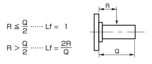
出力軸中実タイプ
作用位置係数(Lf)
アキシャル荷重の確認
出力軸にアキシャル荷重が発生する場合には、各シリーズの許容アキシャル荷重以内かどうか確認してください。
交番荷重について
TDGMの出力軸中空形(パワーロック含む)で、交番荷重が作用する場合は、取付け用のケースタップなどの強度をチェックする必要があります。
作用荷重を確認のうえ、当社までお問合せください。
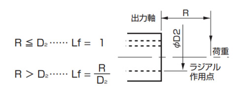
出力軸中空タイプ
作用位置係数(Lf)
7. サイズ・形番の決定
軸荷重が満足しない場合はサイズアップを検討し、軸荷重を再確認のうえ最終形番を選定ください。
