技術資料 減速機 ウォーム減速機 モータ仕様
インバータ駆動について(標準モータでインバータ駆動する場合)
1. 使用周波数範囲
MAX.120Hzです。低Hz域(低周波数)では、インバータの許容範囲内でご使用ください。
2. トルク特性
周波数とトルク特性は下図を参考にしてください。- ・高速域では、kW一定となるためトルクは回転数に反比例して低下します。また回転速度が上がるため、モータ音、モータファン音、減速部音、振動などが増加します。
- ・中速域では、ほぼ定トルク特性となります。
- ・低速域では、モータの運転効率と冷却効果が低下しますので温度上昇は大きくなります。この現象をおさえるためには、下図のようにトルクを低減してご使用ください。
(0.1~0.4kWのみ)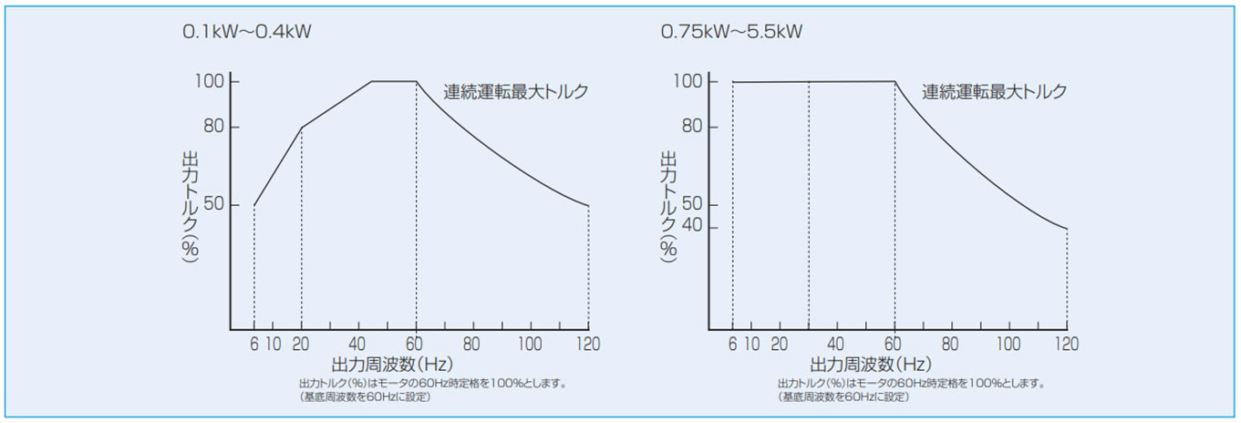
注)上記トルク特性はモータ単体でのものです。
実際にはトロイドライブ・ウォームパワードライブの効率を加味して検討ください。
3. ブレーキ付のとき
- ・ブレーキは所定の電源(周波数、電圧)を必要とするため、結線図を参照してブレーキ回路は別操作としてください。標準品では、ブレーキリード線をモータリード線とネジ止めの状態で出荷していますが、ネジをはずして別々に結線してください。
- ・制動時は60Hz(1800r/min)以下で行ってください。60Hz以上の高速域で制動を行いますと、機械的な損傷やブレーキ部ライニングの異常摩耗の原因にもなりますので、必ず60Hz以下で作動してください。
- ・低速時には冷却能力の低下により耐熱寿命が低下する恐れがあります。その場合はブレーキの電源ON時間率を低減してご使用ください。
4. 注意事項
- ・低周波数および60Hz以上では、上図のようなトルクを低減してご使用ください。
- ・400V級モータをインバータ駆動する場合、インバータのスイッチングにより発生する高電圧のサージ(マイクロサージ)の影響で絶縁破壊が発生する場合があります。よって、これに対する対策(マイクロサージ対策)がモータに必要となりますが、標準400V級モータには、ご指示がない場合でもマイクロサージ対策を施しています。ただし、そのレベルが1250Vを超える場合は、インバータ側へ抑制フィルタやリアクトルを設置してください。
- ・温度上昇・騒音・振動は商用電源時に比べて大きくなります。
- ・モータ過熱保護のため、電子サーマルを汎用モータ特性に設定して使用するかインバータとモータの間にサーマルリレー等を設けてください。
- ・基底周波数50Hzで使用される場合、出力トルクは上表の×0.8としてください。 (0.4kW以下のみ)
- ・回転速度・周波数によってはモータが共振することがあります。連続運転を行う場合は、インバータのキャリア周波数の設定変更などで共振周波数を避けて使用してください。
- ・試運転で負荷が軽い場合、低周波数において、電流値が大きく出ることがあります。これはモータの特性によるもので異常ではありません。インバータの設定変更(トルクブーストを下げる、V/F比を下げる、トルクベクトル制御)を行うことで電流値を下げることができます。
- ・60Hzを超える周波数での連続運転は減速部の発熱が大きくなりますので、避けてください。詳細についてはお問合せください。
インバータモータ付
0.1kW~0.4kWのインバータ対応モータをオプションで用意しています。詳細はお問合せください。
