技術資料 減速機 サーボモータ用減速機TERVO 取扱
ここでは、TERVO HMTK、GMTK、SWJMK、SWMK、EWJMK、EWMKシリーズ取扱に関する一般事項について記載しています。
詳細につきましては、製品に添付しています取扱説明書をご参照ください。
サーボモータの組付け手順
モータ軸がキー軸の場合
- (1)モータ軸にキーが正確にセットされているか確認ください。
- (2)入力軸の内側に付着していますグリースをモータ軸に塗布してください。
- (3)入力軸のキー溝に、モータ軸のキー位置を合わせ挿入ください。
以上でモータのセットは完了です。
モータ軸が丸軸の場合(入力軸クランプタイプ)
- (1)モータ取付け面が上部になるよう減速機を設置ください。
- (2)モータ軸の錆、埃、錆び止め油などはきれいにふきとってください。
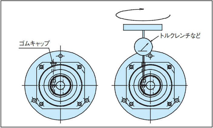
- (3)フランジのキャップを外し、入力軸を回して、ボルトの頭をキャップ位置に合せます。Lスパナなどによりセットボルトが緩んでいることを確認してください。
- (4)モータ軸を入力軸に静かに、スムーズに挿入してください。モータ軸を傾けて挿入しないように十分注意してください。
- (5)インロ部分が完全に挿入された後、適切なボルトを使用し、各ボルトサイズの適切な締付トルクでモータフランジに完全に固定してください。
- (6)入力軸のクランプセットボルトをトルクレンチなどにより、下の表1・2・3の相当する締付トルクで締付けてください。
- (7)キャップを取付けてください。以上でモータのセットは完了です。
表1. GMTK/HMTK クランプ仕様セットボルトの締付トルク
| GMTK | HMTK | セットボルト サイズ |
締付トルク |
|---|---|---|---|
| 0218U/L 0224U/L 0228U/L 0424U/L 0428U/L 0438U/L |
0220H 0222U 0230H 0228U 0430H 0428U 0435H 0438U |
M4 | 4.1N・m {0.41kgf・m} |
| 0728U/L 0738U/L 0742F/L 1538U/L 1542F/L |
0735H 0738U 0745H 0742U 1545H 1542U 1555H 1550U |
M5 | 8.5N・m {0.85kgf・m} |
| 2242F/L | 2245H 2242U 2255H 2250U | M6 | 14N・m {1.42kgf・m} |
表2. SWJMK/SWMK/EWJMK/EWMK クランプセットボルトサイズ一覧
| ウォーム形番 | マウントコード | E4 | G2/G5 | K2/K3/K4 | L1 | |
|---|---|---|---|---|---|---|
| インロ径 | Φ50G7 | Φ70G7 | Φ110G7 | Φ114.3G7/H7 | ||
| 取付ピッチ | PCD70 | PCD90 | PCD145 | PCD200 | ||
| EWJMK35, SWJMK35 | M3 | - | - | - | ||
| EWJMK42, SWJMK42 | M3 | - | - | - | ||
| EWJMK50, SWJMK50 | - | M4 | - | - | ||
| EWJMK63, SWJMK63 | - | M4 | M6 | M6 | ||
| EWJMK70, SWJMK70 | - | - | M6 | M6 | ||
| EWMK80, SWMK80 | - | - | M6 | M6 | ||
| EWMK100, SWMK100 | - | - | - | M6 | ||
表3. SWJMK/SWMK/EWJMK/EWMK クランプセットボルト締付トルク
| クランプセットボルトサイズ | 締付トルク |
|---|---|
| M3 | 1.9N・m {0.19kgf・m} |
| M4 | 3.8N・m {0.39kgf・m} |
| M6 | 12N・m {1.22kgf・m} |
クランプ仕様セットボルトの締付
入力軸クランプタイプへのキー付きモータの取付
キー付きのモータ軸は、キーを取外せば、丸軸と同様にクランプタイプでご使用いただけます。
クランプ部のスリットの位置と 180度反対側にモータのキー溝をセットください。
丸軸の場合と同様の手順で減速機に取付けてください。
