技術資料 減速機 小形ギヤモータ 選定
選定手順や注意事項等をご覧になりたい方は下記へお進みください。
製品シリーズの絞り込みや仮選定をご希望の方は
こちらをクリックしてください。
使用条件が決まっており詳細な選定をご希望の方は
こちらをクリックしてください。
選定例[コンベヤ駆動]
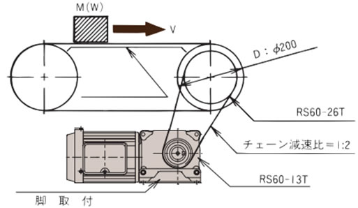
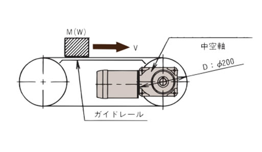
選定例中のA、Bは下図の据付方式、A:脚取付、B:中空軸取付、の場合を示しています。
選定例はハイポイドモートルですが、ギヤモートル、クローゼモータも据付方式に準じて、選定ください。
A:脚取付
|
B:中空軸取付
|
|
選定条件
|
|
1. 減速比の決定
必要とする出力軸回転速度より減速比を決めてください。
決定には特性表の減速比を参照ください。
- A:(1) コンベヤ軸の回転速度(nC)を求めます。
nC = V × 1000 D × π = 14 × 1000 200 × π = 22.3 r/min
- (2) ハイポイドモートルの出力軸回転速度(nL)を求めます。
nL = nC × 2 1 = 44.6 r/min
- (3)減速比を決定します。
製品ページの特性表より、60Hz, 44.6r/minに近い出力軸回転速度を求めると、45r/minとなり減速比は1/40となります。
- B:(1) コンベヤ軸の回転速度(nC)を求めます。
nC = V × 1000 D × π = 14 × 1000 200 × π = 22.3 r/min
- (2) ハイポイドモートルの出力軸回転速度(nL)を求めます。
nL = nC = 22.3 r/min
- (3)減速比を決定します。
製品ページの特性表より、60Hz, 22.3r/minに近い出力軸回転速度を求めると、22.5r/minとなり減速比は1/80となります。
2. 出力軸トルクの算出
負荷トルクより必要とする出力軸トルクを求めてください。
運転条件により表1のサービスファクターを乗じて補正出力軸トルクを求めてください。
- A:(1) コンベヤ軸の必要トルク(TC)を求めます。
TC = 9.8μM D 2 × 1 1000 × 1 η = 9.8 × 0.15 × 150 × 200 2000 × 1 0.95 = 23.2N・m
TC = μW D 2 × 1 1000 × 1 η = 0.15 × 150 × 200 2000 × 1 0.95 = 2.37kgf・m
- (2) ハイポイドモートル出力軸トルク(TL)に換算します。
TL = TC × 1 2 × 1 η = 23.2 × 1 2 × 1 0.95 = 12.2N・m
TL = TC × 1 2 × 1 η = 2.37 × 1 2 × 1 0.95 = 1.25kgf・m
- (3) 出力軸補正トルク(TF)を求めます。
表1のサービスファクターがCF = 1であり TF = TL × 1 = 12.2N・m
{TF = TL × 1 = 1.25kgf・m} - (4) モータ容量を求めます。
製品ページの特性表より、減速比1/40で60Hzのトルク12.2N・m{1.25kgf・m}を満足するものは、0.1kWとなります。
- B:(1) コンベヤ軸の必要トルク(TC)を求めます。
TC = 9.8μM D 2 × 1 1000 = 9.8 × 0.15 × 150 × 200 2000 = 22.1N・m
TC = μW D 2 × 1 1000 = 0.15 × 150 × 200 2000 = 2.25kgf・m
- (2) ハイポイドモートル出力軸トルク(TL)はコンベヤ軸トルクに等しいので TL = TC = 22.1N・m {TL = TC = 2.25kgf・m}
- (3) 出力軸補正トルク(TF)を求めます。
表1のサービスファクターがCF = 1でありTF = TL × 1 = 22.1N・m {TF = TL × 1 = 2.25kgf・m}
- (4) モータ容量を求めます。
製品ページの特性表より、減速比1/80で60Hzのトルク22.1N・m {2.25kgf・m}を満足するものは、0.1kWとなります。
3. 形番の仮定
減速比、トルク、急速停止から
A:ブレーキ付ハイポイドモートル HMTA010-22L40RBと仮定し諸条件を確認します。
B:ブレーキ付ハイポイドモートル HMTA010-20H80Bと仮定し諸条件を確認します。
4. 負荷の慣性モーメント{負荷慣性(GD2)}と起動頻度の確認
負荷の慣性モーメントの大きいものを始動するとき(ブレーキ付の場合は停止時も)に瞬間的に大きなトルクが発生し、思わぬ事故を起因させることがありますので、負荷との連結方法および負荷の慣性モーメント{負荷慣性(GD2)}より検討ください。
- A:(1) コンベヤ軸での負荷の慣性モーメント(IC){負荷慣性(GDC2)}を求めます。
IC = MR2 = 150 × 0.12 = 1.5kg・m2
{GDC2 = WD2 = 150 × 0.22 = 6kgf・m2}R = 1 2 D
- (2) モータ軸相当の慣性モーメント(Iℓ){負荷慣性(GDℓ2)}を算出します。
Iℓ = IC × 1 iC2 × 1 iL2 = 1.5 × 1 2 2 × 1 40 2 = 0.23 × 10⁻³kg・m2
GDℓ2 = GDC2 × 1 iC2 × 1 iL2 = 6 × 1 2 2 × 1 40 2 = 0.94 × 10⁻³kgf・m2
- (3) ハイポイドモートルとの慣性比(U)を求めます。
U = Iℓ IM
U = GDℓ2 GDM2
モータ軸相当慣性モーメント(IM){負荷慣性(GDM2)}は0.66 × 10⁻³kgf・m2{2.64 × 10⁻³kgf・m2}であり
U = 0.23 × 10⁻³ 0.66 × 10⁻³ ≒ 0.35
U = 0.94 × 10⁻³ 2.64 × 10⁻³ ≒ 0.36
- (4) 起動頻度の確認
表3慣性比と許容起動頻度より、起動頻度は30回/時間であり条件を満足します。
- B:(1) コンベヤ軸での負荷の慣性モーメント(IC){負荷慣性(GDC2)}を求めます。
IC = MR2 = 150 × 0.12 = 1.5kg・m2
{GDC2 = WD2 = 150 × 0.22 = 6kgf・m2}R = 1 2 D
- (2) モータ軸相当の慣性モーメント(Iℓ)(GDℓ2)を算出します。
Iℓ = IC × 1 iL2 = 1.5 × 1 80 2 = 0.23 × 10⁻³kg・m2
GDℓ2 = GDC2 × 1 iL2 = 6 × 1 80 2 = 0.94 × 10⁻³kgf・m2
- (3) ハイポイドモートルとの慣性比(U)を求めます。
U = Iℓ IM
U = GDℓ2 GDM2
モータ軸相当慣性モーメント(IM)は0.66 × 10⁻³kgf・m2{2.64 × 10⁻³kgf・m2}であり
U = 0.23 × 10⁻³ 0.66 × 10⁻³ ≒ 0.35
U= 0.94 × 10⁻³ 2.64 × 10⁻³ ≒ 0.36
- (4) 起動頻度の確認
表3慣性比と許容起動頻度より、起動頻度は6回/分であり条件を満足します。
※満足しないときは、期待寿命より早く減速機が損傷することがありますので、形番を上げて再度確認を行うか使用頻度を下げてお使いください。
- ・使用頻度を下げることができないときは、寿命が限定されることになりますのでお問合せください。
- ・慣性比が大きい場合は、インバータなどによる緩起動をお奨めします。
5. オーバーハングロード(O.H.L)の確認
出力軸や入力軸にスプロケット、ギヤ、ベルトなどを取付ける場合には、軸に作用するオーバーハングロードが使用するハイポイドモートルの許容オーバーハングロード(特性表に記載)以下になることを確認ください。
O.H.L を求めます。
O.H.L = 2000TF × f × Lf DS
- A:作用位置を軸長中央とすると、表4. O.H.L係数fおよび式1. 作用位置係数Lfおよび表5. 基準長さQより
f = 1 Lf = 1
RS60-13TのP.C.D = 79.6mmより
O.H.L = 2000 × 12.2 × 1 × 1 79.6 = 307N
O.H.L = 2000 × 1.25 × 1 × 1 79.6 = 31.4kgf
許容O.H.L内にあることを確認します。特性表の許容O.H.Lは1617N{165kgf}でありOKです。
- B:作用位置を下図の中空出力軸端よりℓの位置と仮定すると
f = 1 Lf = 1
O.H.L = 2000 × 22.1 × 1 × 1 200 = 221N
O.H.L = 2000 × 2.25 × 1 × 1 200 = 22.5kgf
許容O.H.L内にあることを確認します。特性表の許容O.H.Lは2254N{230kgf}でありOKです。
※満足しないときは、作用位置を出力軸の根元寄りにしたり、スプロケットのP.C.Dを大きくしたり、ハイポイドモートルの形番を上げて対応してください。
6. 形番の決定
据付方法、使用電源、急速停止の条件とトルク、減速比、起動頻度、O.H.Lを満足するものから次の形番が決定されます。
ブレーキ付ハイポイドモートル
A:HMTA010-22L40RB
B:HMTA010-20H80B
