技術資料 減速機 小形ギヤモータ 選定
選定上の技術資料
1. サービスファクター
特性表の出力軸容量トルクはすべて使用係数を 1.0 とした値です。
運転時間、運転状態、負荷状態に応じて右表よりサービスファクター(Cf)を選定し出力軸補正トルクを算出ください。
表1. サービスファクター:(CF)
| 運転時間 | 10時間以下/日 | 10時間以上/日 | |
|---|---|---|---|
| 運転状態 | 断続・連続 | 断続・連続 | |
| 負荷状態 | 衝撃のない均一負荷 | 1 | 1 |
| 軽い衝撃負荷 | 1 | 1.2 | |
注)中程度、激しい衝撃負荷で使用されるときはご相談ください。
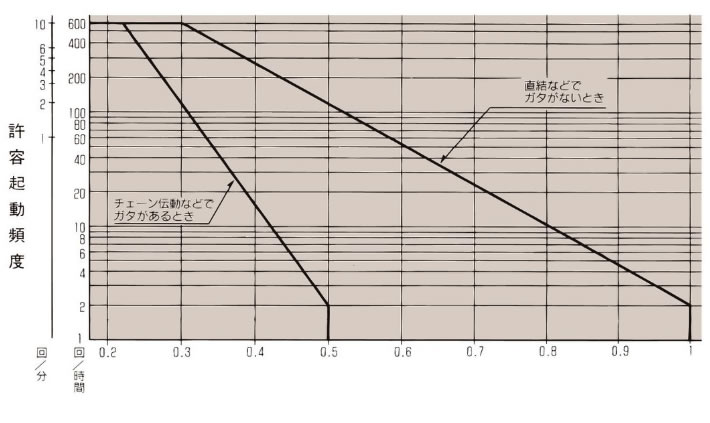
2. 慣性比と許容起動頻度
起動時には負荷慣性により衝撃トルクが発生し(ブレーキ付は制動時も)、負荷と連結方法および負荷慣性の大きさによっては思わぬ事故を起因させることがありますので負荷との連結方法および負荷慣性により、次の手順で確認ください。
- (1)負荷の慣性モーメント(I) {負荷の慣性(GD2)}の算出
- (2)モータ軸換算の負荷の慣性モーメント(IL) {負荷の慣性(GDL2)}算出
- (3)小形ギヤモータとの慣性比(U)を求めます。
U = IL IM
U = GDL2 GDM2
In{GDM2}:小形ギヤモータのモーター軸相当慣性モーメント {モータ軸相当慣性}
- (4)表1、2より許容起動頻度を満足するか確認ください。
表2. クローゼモータ慣性比と許容起動頻度
| 負荷の性格 | 慣性比:U | 許容起動頻度 |
|---|---|---|
| ガタのない場合 | 1 0.5 0.2以下 |
4回/時間 4回/分 10回/分 |
| チェーンなどガタのある場合 | 0.5 0.3 0.2以下 |
4回/時間 4回/分 10回/分 |
注)表2以外の条件の場合は当社へご相談ください。
表3. ギヤモートル、ハイポイドモートル:慣性比と許容起動頻度
慣性比 = モータ軸相当負荷慣性モーメント モータ軸相当ハイポイドモートル・ギヤモートル慣性モーメント
3. 出力軸オーバーハングロードの確認
出力中央軸にスプロット、ギヤ、ベルトなどを取付ける場合、また中空軸にケースタップを使って取付ける場合には、出力軸に作用するオーバーハングロードが、使用する小形ギヤモータの許容 O.H.L. 以下になることを確認ください。
※強力歯付ベルト使用時には表4のO.H.L.係数(f)によらず取付張力を加えて計算してください。
表4. O.H.L.係数f
| チェーン | ギヤ歯付ベルト | Vベルト |
|---|---|---|
| 1.0 | 1.25 | 1.5 |
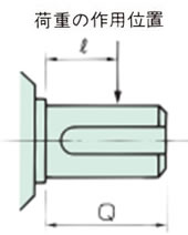
式1. 作用位置係数:Lf
| ℓ/Q | 0.25 | 0.38 | 0.5 | 0.75 | 1 |
|---|---|---|---|---|---|
| Lf | 0.8 | 0.9 | 1 | 1.5 | 2 |
| 中実軸 | 中空軸 (注) |
|---|---|
 |
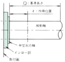 |
注)中空軸のQ:基準長さは下表5を参照ください。
表5. 基準長さ:Q
ハイポイドモートル
| 形番 | 減速比 | Q |
|---|---|---|
| HMMT40H | 5 ~ 240 | 28 |
| HMMS40H | 5 ~ 240 | |
| HMMT60H | 5 ~ 240 | 36 |
| HMMS60H | 5 ~ 240 | |
| HMMT90H | 5 ~ 240 | |
| HMMS90H | 5 ~ 240 | |
| HMAT010-20H | 5 ~ 120 | |
| HMTA020-20H | 5 ~ 60 | |
| HMTA010-30H | 160 ~ 200 | |
| HMTA010-30H | 300 ~ 480 | 42 |
| HMTA020-30H | 80 ~ 200 | |
| HMTA040-30H | 5 ~ 50 | |
| HMTA010-35H | 600 ~ 1200 | 58 |
| HMTA020-35H | 300 ~ 480 | |
| HMTA040-35H | 60 ~ 200 | |
| HMTR075-35H | 5 ~ 50 | |
| HMTA020-45H | 600 ~ 1200 | 66 |
| HMTA040-45H | 300 ~ 480 | |
| HMTR075-45H | 60 ~ 200 | |
| HMTR151-45H | 5 ~ 80 | |
| HMTR221-45H | 5 ~ 60 | |
| HMTA040-55H | 600 ~ 1200 | 82 |
| HMTR075-55H | 300 ~ 480 | |
| HMTR151-55H | 100 ~ 200 | |
| HMTR221-55H | 80 ~ 120 | |
| HMTR370-55H | 5 ~ 60 | |
| HMTR550-55H | 5 ~ 40 |
クローゼモータ
| 形番 | 減速比 | Q |
|---|---|---|
| CSMA010-130H | 10 ~ 60 | 20 |
| CSMA020-130H | 10 ~ 60 | |
| HCMA010-16*H | 40 ~ 200 | 25 |
| HCMA020-16*H | 40 ~ 75 | |
| CSMA040-160H | 10 ~ 30 | |
| CSMA055-160H | 10 ~ 30 | |
| HCMA010-22*H | 240 ~ 300 | 30 |
| HCMA020-22*H | 90 ~ 200 | |
| HCMA040-22*H | 40 ~ 75 | |
| HCMA055-22*H | 40 ~ 50 | |
| CSMA040-220H | 40 ~ 60 | |
| CSMA055-220H | 40 ~ 60 | |
| CSMR075-220H | 10 ~ 30 | |
| HCMA020-28*H | 240 ~ 300 | 40 |
| HCMA040-28*H | 90 ~ 200 | |
| HCMA055-28*H | 60 ~ 150 | |
| HCMR075-28*H | 40 ~ 75 | |
| CSMR075-280H | 40 ~ 60 | |
| CSMR151-280H | 10 ~ 30 | |
| HCMA040-32*H | 240 ~ 300 | 50 |
| HCMA055-32*H | 180 ~ 200 | |
| HCMR075-32*H | 90 ~ 150 | |
| HCMR151-32*H | 40 ~ 50 | |
| CSMR151-32*H | 40 ~ 60 | |
| CSMR221-32*H | 10 ~ 40 | |
| HCMA055-40*H | 240 ~ 300 | 55 |
| HCMR075-40*H | 180 ~ 200 | |
| HCMR151-40*H | 60 ~ 120 | |
| HCMR221-40*H | 40 ~ 75 | |
| CSMR221-40*H | 50 ~ 60 | |
| CSMR370-40*H | 10 ~ 30 | |
| HCMR075-50*H | 240 ~ 300 | 70 |
| HCMR151-50*H | 150 ~ 300 | |
| HCMR221-50*H | 90 ~ 300 | |
| CSMR370-50*H | 40 ~ 60 |
