技術資料 減速機 小形ギヤモータ モータ仕様
標準モータを連続でインバータ駆動する場合
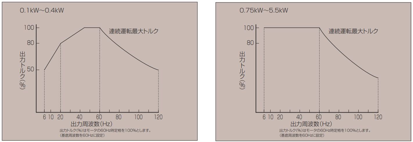
1. 使用周波数範囲
- ・MAX.120Hzです。低Hz域(低周波数)では、インバータの許容範囲内でご使用ください。
- ・40W、60W、90Wは低周波数および60Hz以上の連続運転ではご使用できません。別途ご相談ください。
- ・トップランナーモータ付0.75kW~5.5kWは標準モータで6Hz~60Hzの定トルク運転が可能です。詳細は下記の、トップランナーモータを連続でインバータ駆動する場合をご参照ください。
2. トルク特性
周波数とトルク特性は下図を参考にしてください。
- ・高速域では、kW一定となるためトルクは回転数に反比例して低下します。また回転速度が上昇するため、モータ音、モータファン音、減速部音、振動などが増加します。
- ・低速域では、モータの運転効率と冷却効果が低下しますので温度上昇は大きくなります。下図のようにトルクを下げてご使用ください。
3. ブレーキ付のとき
- ・ブレーキは所定の電源(周波数、電圧)を必要とするため、ブレーキ回路は別操作としてください。標準品では、ブレーキリード線をモータリード線とネジ止めの状態で出荷していますが、ネジをはずして別々に結線してください。
- ・制動時は60Hz(1800r/min)以下で行ってください。 60Hz以上の高速域で制動を行いますと、機械的な損傷やライニングの異常摩耗・発熱などの不具合が発生しますので必ず60Hz以下で作動してください。
4. 単相モータ・防爆モータのとき
- 単相モータはコンデンサーを使用しているため、インバータ駆動はできません。
また、防爆モータは防爆検定申請電源(周波数、電圧)からはずれるため使用できません。
5. 注意事項
低周波数および60Hz以上では、上図のようなトルクを低減してご使用ください。
- ・400V級モータをインバータ駆動する場合、インバータのスイッチングにより発生する高電圧のサージ(マイクロサージ)の影響で絶縁破壊が発生する場合があります。よって、これに対する対策(マイクロサージ対策)がモータに必要となりますが、標準400V級モータには、ご指示がない場合でもマイクロサージ対策を施しています。ただし、そのレベルが1250Vを超える場合は、インバータ側へ抑制フィルタやリアクトルを設置してください。
- ・温度上昇・騒音・振動は商用電源時に比べて大きくなります。
- ・モータ過熱保護のため、電子サーマルを汎用モータ特性に設定して使用するかインバータとモータの間にサーマルリレー等を設けてください。
- ・基底周波数50Hzで使用される場合、出力トルクは上表の×0.8としてください。(0.1kW~0.4kWのみ)
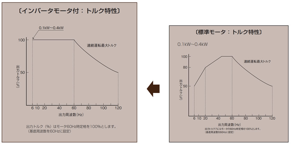
※インバータモータ付
0.1kW~0.4kWではインバータモータ付をオプション対応しています。
インバータモータ付 [オプション記号:Z、ZV]
インバータ駆動時、6~60Hzの範囲で定トルク運転が可能なインバータ専用モータです。
対応容量:0.1kW~0.4kW 標準モータ
| シリーズ | 電圧 | 記号 | モータ容量 | ||
|---|---|---|---|---|---|
| 0.1kW | 0.2kW | 0.4kW | |||
| ギヤモートル ハイポイドモートル クローゼモータ |
200V級 | Z | ○ | ○ | ○ |
| 400V級 | ZV | ○ | ○ | ○ | |
注)定格電圧 [0.1kW~0.4kW:200V級=200/220V 60Hz、400V級=400/440V 60Hz]
※インバータモータ付の注意事項
- ・60~120Hzでは、標準モータと同様に定馬力の特性域となり出力トルクに制限を受けますので負荷トルクには注意が必要です。
- ・インバータからモータへの入力電圧は、インバータの基底周波数・基底電圧を設定し必ず銘板の電圧・周波数になるようにインバータの出力電圧を設定してください。 (インバータモータの場合、基底周波数は60Hzにすることが必要となります。) またインバータモータをインバータを介さずに直入れされますと電圧変動による電流値の増加が激しくなりますので使用は避けてください。 (試運転、緊急時等の短時間の運転は除きます。)また、この現象はとくに50Hz時に顕著に表れます。
- ・インバータのベース周波数は必ず60Hzとしてください。
- ・低周波数で100%トルクが必要な場合は必要に応じてインバータにてトルクブーストをかけて使用してください。トルクブーストをかけ過ぎた状態での長時間の連続運転は過熱の原因となりますので避けてください。
- ・回転速度・周波数によっては、モータが共振することがあります。連続運転を行う場合は、インバータのキャリア周波数の設定変更などで共振周波数を避けて使用してください。
- ・試運転等で、負荷が軽い場合、低周波数において、電流値が大きく出ることがあります。これはモータの特性によるもので異常ではありません。インバータの設定変更(トルクブーストを下げる、V/F比を下げる、トルクベクトル制御)を行うことで電流値を下げることができます。
- ・モータ過熱保護のため、電子サーマルをインバータモータ用特性に設定して使用するかインバータとモータの間にサーマルリレー等を設けてください。
- ・ブレーキ付の場合は、配線図を参照下さい。ブレーキの作動を高速(60Hz以上)で行いますと機械的な損傷やブレーキ部ライニングの異常摩耗の原因にもなりますので、必ず60Hz以下で作動させてください。
トップランナーモータを連続でインバータ駆動する場合
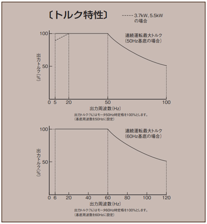
対応容量:0.75kW~5.5kW トップランナーモータ
1. トルク特性
周波数とトルク特性は右図を参考にしてください。
- ・高速域では、kW一定となるためトルクは回転数に反比例して低下します。また回転速度が上昇するため、モータ音、モータファン音、減速部音、振動などが増加します。
- ・低速域では、モータの運転効率と冷却効果が低下しますので温度上昇は大きくなります。
2.ブレーキ付のとき
- ・ブレーキは所定の電源(周波数、電圧)を必要とするため、ブレーキ回路は別操作としてください。標準品では、ブレーキリード線をモータリード線とネジ止めの状態で出荷していますが、ネジをはずして別々に結線してください。
- ・制動時は60Hz(1800r/min)以下で行ってください。
60Hz以上の高速域で制動を行いますと、機械的な損傷やライニングの異常摩耗・発熱などの不具合が発生しますので必ず60Hz以下で作動してください。
3. 注意事項
- ・60Hz基底で60~120Hz・50Hz基底で50~100Hzでは、標準モータと同様に定馬力の特性域となり出力トルクに制限を受けますので負荷トルクには注意が必要です。
- ・インバータからモータへの入力電圧は、インバータの基底周波数・基底電圧を設定し必ず銘板の電圧・周波数になるようにインバータの出力電圧を設定してください。
- ・低周波数で100%トルクが必要な場合は必要に応じてインバータにてトルクブーストをかけて使用してください。トルクブーストをかけ過ぎた状態での長時間の連続運転は過熱の原因となりますので避けてください。
- ・回転速度・周波数によっては、モータが共振することがあります。連続運転を行う場合は、インバータのキャリア周波数の設定変更などで共振周波数を避けて使用してください。
- ・試運転等で、負荷が軽い場合、低周波数において、電流値が大きく出ることがあります。これはモータの特性によるもので異常ではありません。インバータの設定変更(トルクブーストを下げる、V/F比を下げる、トルクベクトル制御)を行うことで電流値を下げることができます。
- ・モータ過熱保護のため、電子サーマルをインバータとモータの間にサーマルリレー等を設けてください。
- ・400V級モータをインバータ駆動する場合、インバータのスイッチングにより発生する高電圧のサージ(マイクロサージ)の影響で絶縁破壊が発生する場合があります。よって、これに対する対策(マイクロサージ対策)がモータに必要となりますが、標準400V級モータには、ご指示がない場合でもマイクロサージ対策を施しています。ただし、そのレベルが1250Vを超える場合は、インバータ側へ抑制フィルタやリアクトルを設置してください。
- ・温度上昇・騒音・振動は商用電源時に比べて大きくなります。
