技術資料 減速機 DCブラシレスモータ 取扱
ここでは、DCブラシレスハイポイドモートル・ドライバに関する一般取扱について記載しています。
詳細につきましては、製品に添付しています取扱説明書をご参照ください。
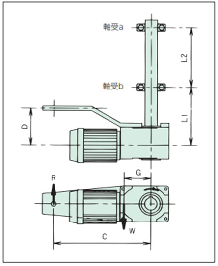
トルクアームの設計
標準トルクアームを用いたり、お客様でトルクアームを設計・製作される場合には、次の要領で各要素の強度を確認してください。
1. トルクアームおよび固定ボルトのチェック
トルクアーム反力Rにより確認してください。
R = T + W × G C
2. 軸受の選定
軸受反力A、Bにより確認してください。
A(軸受a) = L1 × (R - W) -D × R L2
B(軸受b) = (L1 + L2) × (R - W) - D × R L2
*出力トルクは左図回転方向時+、反対方向時は-となります。
- T:出力トルク N・m{kgf・m}
- W:減速機の自重 kg{kgf}
- R:トルクアーム反力 kg{kgf}
- G:被動軸中心と減速機重心間距離 m
- C:被動軸中心と回り止め間の距離 m
- D:減速機中心と回り止め間の距離 m
- L1:減速機中心と軸受b間の距離 m
- L2:軸受aと軸受b間の距離 m
オプショントルクアーム使用時の各寸法(概略値)
| 形番 | DCHM020-20H10~60 | DCHM040-30H10~50 | DCHM075-35H10~50 |
|---|---|---|---|
| G | 0.067m | 0.065m | 0.108m |
