技術資料 小形コンベヤチェーン 選定
倍速チェーンコンベヤ設計資料 以下の寸法を参考に製作、施工ください
1. コンベヤ両端部とスプロケットの位置
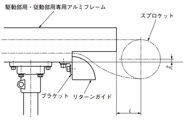
| サイズ&ローラ形式 | レール番号 | Z | L |
|---|---|---|---|
| RF2030VRP | RF2030VRP-R2 RF2030VRP-R2S |
21.3 | 40 |
| RF2040VRP | RF2040VRP-R2 RF2040VRP-R2S |
14.7 | 50 |
| RF2050VRP | RF2050VRP-R2 RF2050VRP-R2S |
16.1 | 60 |
| RF2050VRP-R2HS | 76.2 | 60 | |
| RF2060VRP | RF2060VRP-R2 RF2060VRP-R2S |
14.9 | 70 |
| RF2080VRP | RF2080VRP-R2S | 24 | 100 |
2. アルミフレームの加工寸法
表17のRF2050VRP-R2HSレールには、駆動・従動部用アルミフレームがありません。
表17の寸法を参考に中間フレームを追加工ください。
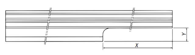
| サイズ&ローラ形式 | RF2050VRP |
|---|---|
| レール番号 | RF2050VRP-R2HS |
| X(駆動側) | 340 |
| X(従動側) | 120 |
| Y | 30 |
3. 取付ボルト・コンベヤ高さ
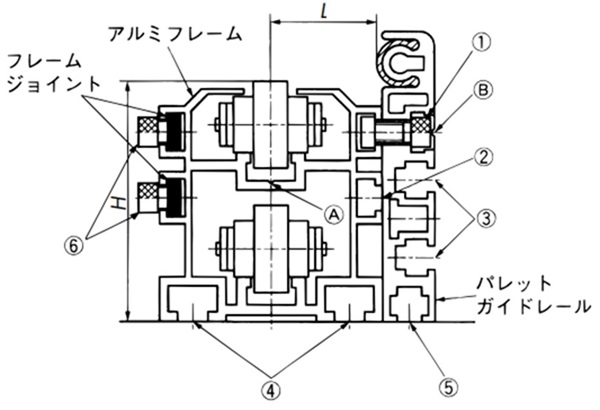
| フレーム | (1) | (2) | (3) | (4) | (5) | (6) | H | L |
|---|---|---|---|---|---|---|---|---|
| RF2030VRP-R2 RF2030VRP-R2S |
M6×10 | M6 | M5 | M6 | M5 | M6×8 | 61.5 | 14.5 |
| RF2040VRP-R2 RF2040VRP-R2S |
M6×12 | M6 | M6 | M8 | M6 | M6×8 | 68 | 28.5 |
| RF2050VRP-R2 RF2050VRP-R2S |
M8×20 | M8 | M8 | M10 | M8 | M8×10 | 82.5 | 36 |
| ※RF2050VRP-R2HS | M8×20 | M8 | M8 | M10 | M8 | M8×10 | 142.5 | 37 |
| RF2060VRP-R2 RF2060VRP-R2S |
M8×20 | M8 | M8 | M10 | M8 | M8×10 | 95 | 44.5 |
| RF2080VRP-R2S | M8×25 | M8 | M8 | M10 | M8 | M8×12 | 130 | 47 |
- 1) アルミフレーム間の位置合わせ
上図矢印(A)のV溝を基準に位置を合わせ、表18(4)のボルトでベースに固定ください。 - 2) アルミフレームの接続
位置合わせの後、フレームジョイントで固定できます。
※フレームジョイントはアルミフレーム間の位置合わせ用ではありません。 - 3) パレットガイドレールの取付け
図矢印(B)のV溝の位置に必要な大きさの穴をあけて、表18(1)の六角ボルトで取付けてください。 - 4) 上表の※印はアルミフレームとパレットガイドレールには60mmの高さの差が生じます。
パレットガイドレールの下に高さ調整のカラーを入れてご使用ください。
4. コンベヤ脚ピッチ
搬送物質量と表19の断面二次モーメントによって決定してください。ただし、断面二次モーメントにかかわらず、フレーム連結部は脚で受けるよう設計ください。
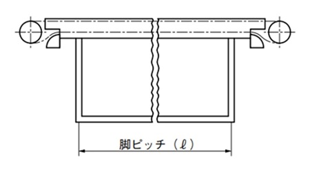
脚ピッチの求め方(ℓ)
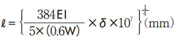
- I = 断面二次モーメント(cm4)(表19参照)
- W = 積載質量(kg/m)
- δ = たわみ(2mm)
- E = 7.0 × 10³ (kg/mm2)
注)積載質量(W)は、チェーンを2本並列で使用するため、負荷のアンバランスを考慮して積載質量の(0.6W)とします。
| 分類 | フレーム形番 | 断面二次モーメント(I) cm4 |
|---|---|---|
| アルミフレーム | RF2030VRP-R2 | 17.127 |
| RF2040VRP-R2 | 40.185 | |
| RF2050VRP-R2 | 84.039 | |
| RF2060VRP-R2 | 135.137 | |
| スチールレール付 アルミフレーム |
RF2030VRP-R2S | 17.821 |
| RF2040VRP-R2S | 44.312 | |
| RF2050VRP-R2S | 95.623 | |
| RF2050VRP-R2HS | 442.093 | |
| RF2060VRP-R2S | 171.761 | |
| RF2080VRP-R2S | 360.726 |
※駆動・従動部用フレームも断面二次モーメント(I)は上記と同じです。
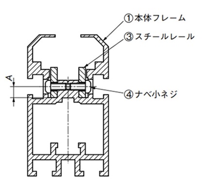
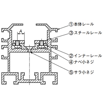
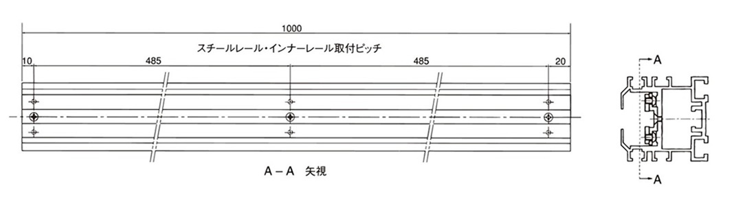
5. スチールレール付アルミフレーム
1)断面構造
RF2030VRP
RF2040VRP~RF2080VRP
| フレーム形番 | スチールレール(品番3) | スチールレール取付ネジ (品番4) 十字穴付ナベ小ネジ |
インナーレール取付ネジ (品番5) 十字穴付サラ小ネジ |
||
|---|---|---|---|---|---|
| 中間用 | 駆動・従動用 | 寸法 (板厚×幅) |
A寸法 | ||
| RF2030VRP-R2S | RF2030VRP-R1SK, -R1SJ | 3×13 | 4.75 | M3×7 | - |
| RF2040VRP-R2S | RF2040VRP-R1SK, -R1SJ | 3×13 | 8.4 | M4×5 | M4×6 |
| RF2050VRP-R2S | RF2050VRP-R1SK, -R1SJ | 3×13 | 8.4 | M4×6 | M4×6 |
| RF2050VRP-R2HS | - | 3×13 | 8.4 | M4×6 | M4×6 |
| RF2060VRP-R2S | RF2060VRP-R1SK, -R1SJ | 3×13 | 8.4 | M4×6 | M4×6 |
| RF2080VRP-R2S | RF2080VRP-R1SK, -R1SJ | 6×16 | 10.5 | M5×8 | M6×10 |
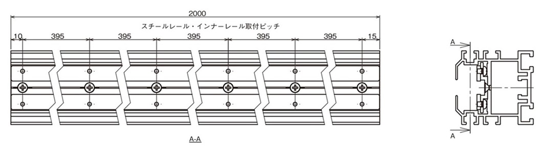
2)中間用フレーム組立図
3)駆動部用、従動部用フレーム組立図
- ・RF2050VRP-R2HSには、駆動・従動部用フレームはありません。
- ・上図の右端部の下側には、切込み加工が施してあります。(RF2030VRP-R1Kの例)
4)スチールレール付アルミフレーム取扱留意点
- 1. スチールレール付アルミフレームを切断して使用する場合
- (1)フレーム中央部、あるいはネジ部以外を切断します。
- (2)切断した面に発生したバリなどは除去します。
- (3)切断した面から15~30mmのところでスチールレールとインナーレール、およびインナーレールと本体フレームをビス止め固定します。
- (4)加工はすべて部品単体で行い、加工によって発生したバリ・キリコなどは完全に除去して再組立を行います。45°カット部も食い違いがないようにしてください。
- 2. フレーム連結の場合
フレーム連結後、スチールレールの合わせ面に段差(縦、横方向)がある場合は、チェーンのローラが引っ掛からないようにわずかな面取りを施してください。
