技術資料 大形コンベヤチェーン 選定
10. 選定例
10.1 ベアリングローラコンベヤチェーン
ベアリングローラコンベヤチェーンとコンベヤチェーンDT仕様の各々について選定します。
1) 必要チェーンリンク数
n = 50000 250 × 2 + 12 × 2 = 412 × 2 = 824リンク
2) ローラ負荷の確認
ローラ有効個数 = 搬送物長さ チェーンピッチ = 1000 250 = 4個
チェーン2条のため、全数で8個あるが偏荷重を考慮し4個有効とする。
ローラ負荷 = 2000 × g 1000 × 1 4 = 4.9kN {500kgf}/個
表11より、ベアリングローラコンベヤチェーンはRF12250BF-1LA2-許容負荷5.49kN {560kgf}
RF形コンベヤチェーンは、RF26250F-DT-1LA2-許容負荷5.30kN {540kgf}が選定できる。
3) コンベヤ上の許容積載質量の確認
簡易選定のため、起動時の衝撃力と自重による引張力を無視すると、2000kg × 40個/2条 = 40000kg/条
右表より、ベアリングコンベヤチェーンは、RF10トンサイズ-53300kg。コンベヤチェーンは、RF17トンサイズ-44600kgが選定できる。
ローラ許容負荷と積載質量を比較すると、ローラ許容負荷による選定が優先となる。
潤滑状態での使用を前提とし、ローラ回転不良や早期摩耗を生じない目安の値です。使用条件(高速・大荷重・長時間運転)と期待寿命によっては、許容値に対して余裕を見て選定してください。
潤滑状態での使用を前提とし、ローラ回転不良や早期摩耗を生じない目安の値です。使用条件(高速・大荷重・長時間運転)と期待寿命によっては、許容値に対して余裕を見て選定してください。
ベアリングローラコンベヤチェーン(f1=0.03とする)
T = 2000kg × g 1000 × 40個 × 0.03 = 23.5kN{2400kgf}
コンベヤチェーン(f1=0.08とする)
T = 2000kg × g 1000 × 40個 × 0.08 = 62.8kN{6400kgf}
ベアリングローラコンベヤチェーン

コンベヤチェーン

4) モータのサイズ選定(動損失を1割とする)
モータ kW = T × V 60 × 1.1 × 1 η = (η = 0.85とする) より
ベアリングローラコンベヤチェーン所用動力
kW = 23.5 × 10 60 × 1.1 × 1 0.85 = 5.1kW
コンベヤチェーン所用動力
kW = 62.8 × 10 60 × 1.1 × 1 0.85 = 13.5kW
許容積載質量早見表
|
コンベヤチェーン サイズ |
コンベヤチェーン (DT) |
ベアリングローラ コンベヤチェーン (DT) |
|---|---|---|
| RF03 | 5400 | 14000 |
| RF05 | 12500 | 33300 |
| RF08・450 | 14300 | 36700 |
| RF10 | 20500 | 53300 |
| RF12 | 33900 | 90000 |
| RF17 | 44600 | 116700 |
| RF26 | 57100 | 150000 |
| RF36 | 86600 | 230000 |
| RF60 | 91100 | - |
| RF90 | 143800 | - |
| RF120 | 201800 | - |
注)水平コンベヤで摩擦係数 [コンベヤチェーン:0.08/ベアリングローラ:0.03]
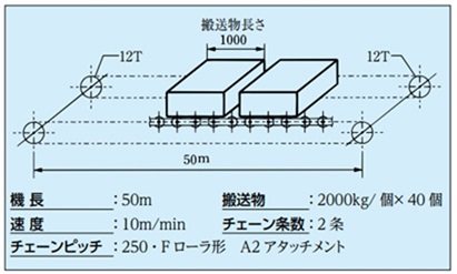
10.2 コンベヤ形式:スラットコンベヤ(水平)
- 搬送物:箱状の荷物
- 機長:30m
- 積載量:搬送物を1m毎に1個のせる
- 使用スプロケット:12T
- 使用チェーン:ピッチ100、各リンクA2のFローラ形チェーンとする
- 使用時間:8時間/日
- スラット質量:10kg/枚
- チェーン条数:2条
- 搬送物質量:100kg/個
- チェーン速度:15m/min
- 使用環境:常温
1) 必要チェーンリンク数:n
n = 30000 100 × 2 + 12 × 2 = 612 × 2 = 1224リンク
2) チェーンのサイズ
コンベヤ上に搬送物が30個のる。コンベヤ上の全積載質量は、100 × 30 = 3000kg、摩擦係数は潤滑状態が条件であるから表5より0.08とする。
搬送物のみ移動するに要する力T1は
T1 = 3000 ×
g
1000
×
0.08 = 2.35kN {T1 = 3000 × 0.08 = 240kgf}
次に、スラット質量は10kg/枚、ピッチ100であるから、スラット質量 = 10 × 1000 100 = 100kg/mとなる。
スラットのみ移動させるに要する力T2は
T2 = 2.1 × 100 × 30 ×
g
1000
×
0.08 = 4.94kN {T2 = 2.1 × 100 × 30 × 0.08 = 504kgf}
T1 + T2 = 2.35 + 4.94 = 7.29kN {T1 + T2 = 240 + 504 = 744kgf}
RF03100F-DTの2条の最大許容張力は、4.20kN × 2条 = 8.40kN{860kgf}であるから使用できそうである。
潤滑状態での使用を前提とし、疲労破壊、摩耗を加味した限界値です。弊社カタログに記載された選定を基に補正チェーン張力を求め、この値以下でお使いいただいた場合、早期に異常を生じることはありません。 ただし、特殊雰囲気における性能低下を生じた場合は除きます。
チェーンのサイズは、RF03100F-DT-1LA2とすると、チェーンのみ移動させるに要する力T3は、
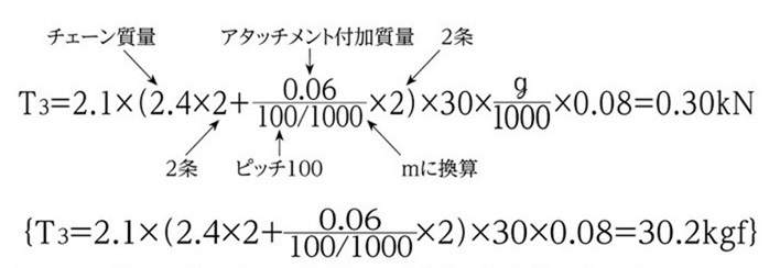
TMAX = T1 + T2 + T3 = 2.35 + 4.94 + 0.30 = 7.59kN
{TMAX = T1 + T2 + T3 = 240 + 504 + 30.2 = 774kgf}
2条のチェーンに作用する負荷が均等と仮定した場合、チェーン1条の補正チェーン張力T'MAX
T'MAX = 7.59/2条 × Kv × KT × Ks = 7.59/2 × 1.0 × 1.0 × 1.0 = 3.80kN
RF03100F-1LA2 1条の最大許容張力は4.20kNのため、T'MAX = 3.80kN < 4.20kN
潤滑状態での使用を前提とし、疲労破壊、摩耗を加味した限界値です。弊社カタログに記載された選定を基に補正チェーン張力を求め、この値以下でお使いいただいた場合、早期に異常を生じることはありません。 ただし、特殊雰囲気における性能低下を生じた場合は除きます。
ローラ許容負荷およびアタッチメントの許容負荷は、表10、11を満足する。
潤滑状態での使用を前提とし、ローラ回転不良や早期摩耗を生じない目安の値です。使用条件(高速・大荷重・長時間運転)と期待寿命によっては、許容値に対して余裕を見て選定してください。
A形アタッチメントが許容できる垂直荷重です。Kアタッチメントをご使用の場合は、Aアタッチメント許容負荷の2倍で計算ください。お客様で取付けられるアタッチメントの形状・構造によっては、Aアタッチメントを捩じる力が発生する場合が有りますので、懸念事項がある際にはお問合せください。

3) 駆動スプロケットトルク:Tr
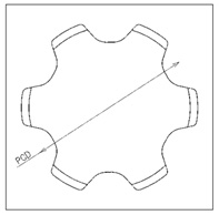
ピッチ100、N = 12Tのスプロケットのピッチ円直径はΦ386.4
Tr = 7.59 × 386.4 × 1 2 × 1 1000 = 1.47kN・m
{Tr = 774 × 386.4 × 1 2 × 1 1000 = 149.5kgf・m}
4) 所要動力
kW = 7.59×15 60 × 1.1 × 1 0.85 = 2.46kW
{kW = 774 × 15 102 × 60 × 1.1 × 1 0.85 = 2.46kW}
10.3 コンベヤ形式:連続式バケットエレベータ(垂直)
- 揚程:30m
- 使用チェーン:ピッチ250、2リンク毎GA4アタッチメント付
(Sローラ形バケットエレベータ用) - 搬送容量:90t/h
- バケット質量:25kg/個
- 使用スプロケット:N = 12T
- 使用環境:常温
- 使用時間:8時間/日
- チェーン速度:28m/min
- 潤滑:無潤滑の状態
- 編成:左右半数勝手違い
1) 必要チェーンリンク数:n
n = 30000 250 × 2 + 12 × 2 = 252 × 2 = 504リンク
2) チェーンサイズ
(1) 搬送物のみによる張力 T1
T1 = 16.7 × 90 28 × (30 + 1) × g 1000 = 16.3kN
{T1 = 16.7 × 90 28 × (30 + 1) = 1664kgf}
部:搬送物を積載する際の荷重増を考慮してスプロケットの中心距離を1m増して計算 (チェーンに作用する張力の計算方法:垂直搬送 参照)
(2) バケットのみによる張力 T2
チェーンピッチ250で、バケットは2リンク毎に取付くのでバケット質量は25kg × 2 = 50kg/mとなる。
T2= 50 × g 1000 × (30 + 1) = 15.2kN
{T2= 50 × (30 + 1) = 1550kgf}
(3) T1 + T2 = 16.3 + 15.2 = 31.5kN
{T1 + T2 = 1664 + 1550 = 3214kgf}
ここで、チェーン2条で最大許容張力を満足しうるチェーンとしてB17250S(最大許容張力35kN)を仮選定する。
潤滑状態での使用を前提とし、疲労破壊、摩耗を加味した限界値です。弊社カタログに記載された選定を基に補正チェーン張力を求め、この値以下でお使いいただいた場合、早期に異常を生じることはありません。 ただし、特殊雰囲気における性能低下を生じた場合は除きます。
B17250S 2リンク毎GA4アタッチメントのチェーン質量は15kg/mであるから
2条
↓
T3 = 15 × 2 × (30 + 1) × g 1000 = 9.12kN
{T3 = 15 × 2 × (30 + 1) = 930kgf}
(4) 搬送物の左右チェーンに対する偏荷重を6:4と仮定した場合、チェーン1条のチェーン張力TMAXは
16.3 × 0.6 + 15.2 2 + 9.12 2 = 21.9kN
{1664 × 0.6 + 1550 2 + 930 2 = 2238kgf}
無潤滑のため摩耗寿命に配慮し、1.5の余裕を見込み
補正チェーン張力 T'MAX = 21.9 × Kv × KT × Ks × 1.5 = 21.9 × 1.05 × 1.0 × 1.0 × 1.5 = 34.5kN
{T'MAX = 2238 × 1.05 × 1.0 × 1.0 × 1.5 = 3524kgf}
以上よりB17250S-CT-2LGA4となる。

注)条間の偏荷重は搬送条件により異なるので、実際のご使用条件に即した値をご採用ください。
3) 駆動スプロケットトルク:Tr
垂直バケットエレベータの場合、チェーン質量とバケット質量はバランスしている。したがってトルク、所要動力に関係する張力は、搬送物による張力T1のみである。
ピッチ250、N = 12Tのときのピッチ円直径Φ965.9であるから
スプロケットの歯形ピッチに外接する円の直径。
(JIS B 1812:2015)
Tr = 18.1 × 965.9 × 1 2 × 1 1000 = 8.74kN・m
{Tr = 1849 × 965.9 × 1 2 × 1 1000 = 893kgf・m}
4) 所要動力:Tr
kW = 18.1 × 28 60 × 1.1 × 1 0.85 = 10.9kW
{kW = 1849 × 28 102 × 60 × 1.1 × 1 0.85 = 10.9kW}
