技術資料 ドライブチェーン 用語説明
1. JIS最小引張強さ(引張破断強度)
JISで定められている最小引張強さ。JIS品としては、これより低い荷重で破断すると不合格になります。多列のローラチェーンは単列の列数倍となります。(JIS B 1801 : 2014)
またISOに準拠したものとなっています。(ISO 606 : 2004)
2. 最小引張強さ
当社実績より統計処理して決めた最小値です。任意のローラチェーンを引張試験した場合、この値より低い荷重で破断すると不合格になります。この値はメーカにより異なります。
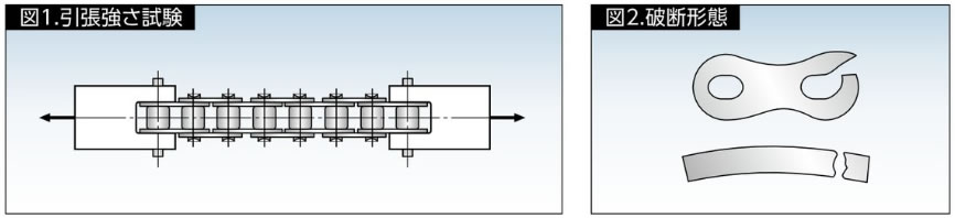
試験方法
図1のように有効部分が5リンク以上のローラチェーンの両端を治具で固定して、破断にいたるまで引張ります。(JIS B 1801 : 2014)
破断形態は、ローラチェーンの分解または部品の破壊(図2)です。
3. 最大許容張力
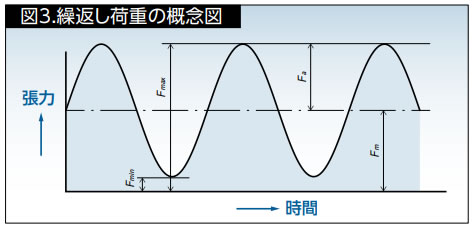
ローラチェーン(ステンレス製とエンプラ製*を除く)の最大許容張力は、疲労限度になります。この値以下の荷重であれば、繰り返し負荷をかけてもローラチェーンの疲労破壊は起こりません。
JIS B 1811:2018では、直線状態で図3の繰り返し荷重を受けた場合、有効5リンク以上のローラチェーンが、107回数(1千万回)での破壊確率を0.135%として計算した時の最小張力を0に合わせて補正した試験張力(Fd)を表します。
*ステンレス製とエンプラ製は、ピンとブシュの間の面圧を摩耗性能から規定し、最大許容張力を決定しています。
オフセットリンクは、ローラチェーンの本体よりも強度が低下することがあります。
Fd = Fu(Fmax - Fmin) Fu - Fmin
Fu:JIS最小引張強さ
4. 伝動能力表
RSローラチェーンとスーパチェーン、強力チェーン、低騒音チェーンの伝動能力表は、下記(1~5)の条件でローラチェーン100リンクの2軸伝動を行い、15,000時間まで耐える伝動kWを示しています。
- 1) -10℃~60℃の室内雰囲気中で運転され、粉塵がないこと。
- 2) 腐食性のガス、多湿などの環境による悪影響がないこと。
- 3) 伝動する2軸が水平で、適切な配置据付が行われていること。
- 4) 負荷変動の少ない伝動であること。
- 5) RSローラチェーンとスーパチェーン、強力チェーン、低騒音チェーンは伝動能力表の推奨潤滑形式で、使用条件に適した潤滑油を使用すること。
5. 慣性モーメント
回転運動における慣性、つまり“回りにくさ”、あるいは“回りやすさ”の程度を表わす場合に慣性モーメント(イナーシャ)を用います。
これは直線運動をする物体の質量(重量)に相当します。
SI単位系における慣性モーメントは、I = MK2(kg・m2 M:回転体の質量 K:回転半径)で与えられます。
また重力単位系における慣性モーメントI は、 I = G・K2 G (kgf・m・S2 G:回転体の重量 G:重力加速度)で与えられます。
一般にGD2 = 4G I (D:回転体の直径)として、慣性モーメントの代わりに用いられてきました。
6. ローラチェーンの全長公差
JIS B 1801 : 2014には、長さの試験方法、長さの許容差が決められています。
各サイズJISで決められた測定荷重(RS80-1の場合、500N)をかけたときの長さの許容差は、基準の長さの0~ + 0.15%にするとあります。
基準長さとは、チェーンピッチの基準値(P)×リンク数で算出します。(JIS呼び番号記載品に適用)
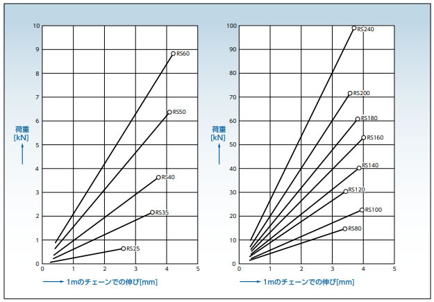
7. 荷重によるチェーンの弾性伸び
チェーンに荷重をかけたときの弾性伸び線図は下図のようになります。ここに示した値は、1列のRSローラチェーンの標準的な目安値です。
なお、最大許容張力を超える荷重はローラチェーンにかけないでください。