技術資料 ドライブチェーン ローラチェーンの取扱
7. ローラチェーンの点検
- 1. 一般にローラチェーンの寿命は、部品が損傷したり、ローラチェーンが1.5%の摩耗伸びを生じたときとします。寿命に至るまでにローラチェーンを取替えてください。
- 2. ローラチェーンは使用に伴い、ピンとブシュの摩耗が少しずつ進行します。
7.1 点検のステップ
| ステップ | 方法 | 点検項目 | 詳細参照ページ |
|---|---|---|---|
| ステップI | 目視で運転状況に異常がないか点検する。 |
|
点検要領は下記およびトラブルシューティングの頁 |
| ステップII | 運転を止め、ローラチェーンとスプロケットの各部を細かく点検する。 |
|
|
| ステップIII | さらに詳細に調べるためローラチェーンを外し、測定器も用いて点検する。 |
|
7.2 点検の間隔
ローラチェーンは、1ヵ月稼働ごとの定期点検を推奨します。
次の場合は更に短い周期で定期点検を行っていきます。
- 1. 特殊な雰囲気や、雰囲気の悪い所
- 2. 高速運転で急停止する場合
- 3. 吊下げ、間欠運転の場合
7.3 巻き掛け伝動の点検要領
1. 給油状況の点検
- 1-1. 運転中は、潤滑油が外プレートと内プレートの隙間に入っているかどうか。
またオイルバスでは、ローラチェーンまたは回転板が潤滑油に浸っているかどうかを調べます。 - 1-2. 給油不足のローラチェーンは、一般に表面が摩耗粉などで汚れています。
特にプレートの隙間で汚れが目立ちます。 - 1-3. 取外したローラチェーンは、継手リンクのピンとその端部、内リンクのブシュ内面を調べます。
表面がむしれたり、赤色や暗褐色をしている場合は給油不足です。
2. プレートの点検
- 2-1. ローラチェーンに最大許容張力よりも大きな力が繰り返しかかると、疲労破壊が起こります。外観観察から、疲労破壊による初期のクラックを発見することは困難です。
- 2-2. クラックは、一般に図25のようにプレートの穴の縁、または側面から発生します。綿密にクラックの発生を点検してください。疲労破壊は徐々に進行しますが、注意深く観察することで発見することができます。
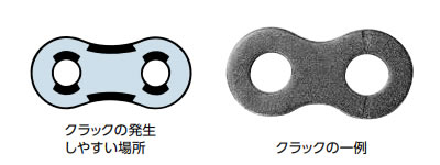
図25. プレートのクラック
- 2-3. プレートの端面がガイドなど、接触箇所との摺動によって摩耗しているときは、据付状態を修正してください。このときの摩耗限界は、プレート高さの5%までとします。(図26)
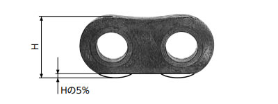
図26. プレート端面の摩耗
3. ピンの点検
ピンが回転(図27)しているときは、ローラチェーン全体を新品に取替えてください。継手リンクのピンについても同様です。継手リンクを外すことで、ピン表面の摩耗と発錆状態を見ることができます。
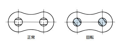
図27. ピンの回転
4. ローラの点検
- 4-1. プレートと同様にローラも最大許容張力より大きな力がかかると、スプロケットとの繰り返し衝撃荷重が大きくなり、疲労破壊が起こります。
(図28)
これもプレートのクラックと同様に点検を行います。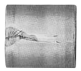
図28. ローラのクラック
- 4-2. スプロケットとの噛み合い、特に異物を噛み込んだ場合、ローラに傷が付き、疲労破壊の起点となります。
なお、高速運転では、異物を噛み込まなくても、スプロケット歯面との衝突によって、クラックが入ることがあります。 - 4-3. ローラが疲労破壊したローラチェーンは、各部分が同様の繰り返し荷重を受けているため、ローラチェーンを全部取替えてください。
- 4-4. ローラの回転不良がないかについても確認を行ってください。
5. スプロケットの点検
- 5-1. ローラチェーンとスプロケットの噛み合いが正常かどうかは、ローラと歯面の当たりの状態を観察します。
正常な噛み合いは、当たりの状態が図29のAのように一様に当たっています。
Bのように偏ったものや、歯の側面が当たって削られているときは、スプロケットの取付不良や、ローラチェーンがねじれている場合があります。再点検、修正を行います。 - 5-2. 当たりの位置は、歯底(谷)から少し上った所が正常です。図29のように、Aの位置に強い当たりが見られます。
ただし、初期張力を与えてたるみ側にも張力がある場合には、わずかに歯底にも当たります。 - 5-3. アイドラとテンショナは、歯底に当たります。
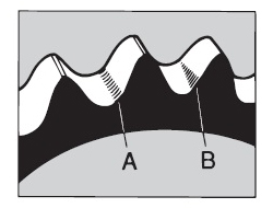
A:正常 B:取付不良

歯の側面が当たって削られている
...取付不良図29. スプロケット歯面の当たり
- 5-4. スプロケットの寿命は、歯部の摩耗が下表の値になったときです。
歯先硬化仕様スプロケットについては、硬化層がなくなったときです。歯厚の使用限界・B寸法
RSローラチェーン
サイズB寸法 B寸法 ピンギヤ RS11-SS 0.6 - RS15 1.1 - RS25 1.5 - RS35 2.5 - RS41 2.6 - RS40 2.5 3.1 RS50 2.9 3.6 RS60 3.7 4.6 RS80 5.0 6.3 RS100 6.9 8.6 RS120 8.7 10.9 RS140 10.6 13.3 RS160 12.4 15.5 RS180 11.3 14.1 RS200 12.6 15.8 RS240 15.1 18.9 RF320-T 19.9 24.9 RF400-T 24.9 31.2 RSローラチェーン
サイズ
BS/DIN規格B寸法一般 RF06B 1.6 RS08B 2.1 RS10B 2.9 RS12B 3.6 RS16B 5.0 RS20B 6.8 RS24B 7.2 RS28B 8.6 RS32B 11.9 RS40B 12.7 
正逆転のとき
一方向回転のとき
図30. B寸法の位置
- 5-5. 摩耗したスプロケットに新品のローラチェーンをかけると、急速にローラチェーンが摩耗します。
新しいローラチェーンへ取替えるときは、スプロケットも同時に取替えてください。
6. チェーンの伸びの点検
- 6-1. ローラチェーンの伸びは、プレートが変形して伸びるのではなく、ピンとブシュの摺動面が摩耗して、遊びが大きくなり全体として伸びた状態になります。
したがって、定期的にローラチェーンの伸びを測定して、寿命を予測することができます。 - 6-2. 測定要領
- (1)ローラチェーン全体の遊びを除くために、ある程度引っ張った状態で測定します。
- (2)図のように測定するリンク数のローラ間の内側(L1)と外側(L2)を測定し、判定寸法(L)を求めます。
L = L1 + L2 2
- (3)測定に際しては、測定誤差をできるだけ少なくするために、6~10リンク程度で測定します。
図31. 長さの測定
- (4)次にチェーンの伸びを求めます。
チェーンの伸び = 判定寸法 - 基準長さ 基準長さ × 100(%)
基準長さ = チェーンピッチ × リンク数
- (5)多列ローラチェーンも同一ピッチの単列ローラチェーンと同様に行います。
- (6)円滑なローラチェーン伝動を期待する場合の、ローラチェーン伸びによる使用限界は次のとおりです。
伸びの使用限界 大スプロケット歯数 チェーンの伸び 60歯以下 1.5% 61~80歯以下 1.2% 81~100歯以下 1.0% 101~110 0.8% - (7)基準長さ(チェーンピッチ×リンク数)と1.5%伸びの判定寸法は下表のとおりです。
- (8)ローラチェーンの長さをノギスで測れないときは、巻尺でも測れますが、測定誤差を少なくするために、測定リンク数を多くします。
- (9)ラムダチェーン・長寿命ラムダチェーンは、チェーン伸びが0.5%位になったとき、油切れになることがあります。油切れの目安として、プレート間に赤い摩耗粉が付き、屈曲不良も発生します。
基準長さと1.5%伸び寸法 6リンクの判定の場合 10リンクの判定の場合 基準長さ 判定寸法 基準長さ 判定寸法 RS25 38.10 38.67 63.50 64.45 RS35 57.15 58.01 95.25 96.68 RS41 76.20 77.34 127.00 128.91 RS40 76.20 77.34 127.00 128.91 RS50 95.25 96.68 158.75 161.13 RS60 114.30 116.01 190.50 193.36 RS80 152.40 154.69 254.00 257.81 RS100 190.50 193.36 317.50 322.26 RS120 228.60 232.03 381.00 386.72 RS140 266.70 270.70 444.50 451.17 RS160 304.80 309.37 508.00 515.62 RS180 342.90 348.04 571.50 580.07 RS200 381.00 386.72 635.00 644.53 RS240 457.20 464.06 762.00 773.43
7.4 吊下げ・台車けん引などの点検
- 1. 前項(7.3)巻き掛け伝動と同じ要領で実施します。
- 2. スプロケットにローラチェーンが巻き付いて屈曲する箇所、および端末金具が付いている箇所は、ローラチェーンと端末金具との接続部の給油状態を調べることが大切です。
- 3. ローラチェーンの摩耗伸びを点検するときは、スプロケットにローラチェーンが巻き付いて屈曲する箇所を調べてください。
- 4. ローラチェーンのねじれ、横曲りの点検局部的なねじれや、横曲がりがあれば、一連のローラチェーンのすべてを取替えてください。(図32)
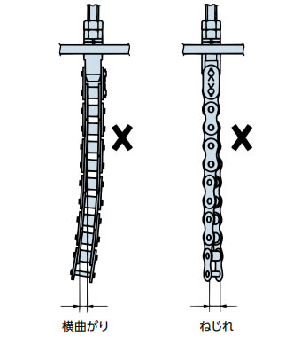
図32. ローラチェーンのねじれ
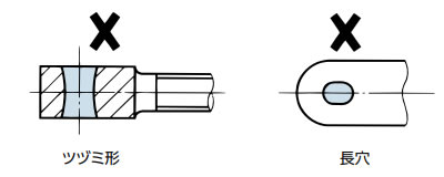
- 5. 端末金具
連結部の穴に摩耗、変形、損傷がないか確認します。変形、損傷していれば、直ちに取替えてください。
金具のピン穴の隙間は、ローラチェーンの寿命を左右しますので、極力少なくなるように設計します。
7.5 保管
ローラチェーン、スプロケット、端末金具などの補充部品は高温多湿の場所、粉塵のある場所を避けて保管します。
また、取外したローラチェーンを保管する場合は、ローラチェーンを洗浄してから潤滑油に浸し、ローラチェーンの隙間に潤滑油をよく浸み込ませた後、油紙で完全に包装し保管します。
