技術資料 高速リフタ ジップチェーンリフタ ストローク制御
ストローク制御
リフタは『ストローク』内で使用してください。
(ストローク≧使用ストローク)

位置検出センサ仕様(ZSL1000)
| ストローク調整用リミットスイッチ | |
|---|---|
| メーカ | オムロン(株) |
| リミットスイッチ形式 | WLCA12-2-N(OMRON)相当品 |
| 電気容量 | AC250V 10A(cosΦ=0.4) DC5V 1mA(最小適用負荷) |
| 回路構成 | 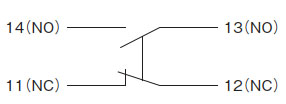 |
| コネクタ(適合ケーブル外径) | SCS-10B(Φ8.5~Φ10.5)PF1/2 |
位置検出センサ仕様(ZSL0050)
| 下減速・下限停止 | |||
|---|---|---|---|
| メーカ | オムロン(株) | ||
| フォト・マイクロセンサ | EE-SPX303N | ||
| 入出力段 回路図 |
しゃ光時ON | タイム チャート |
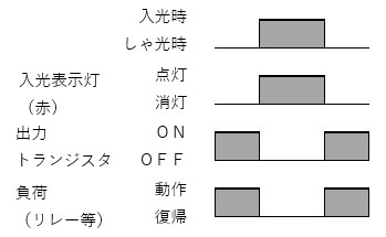 |
| 出力回路 | 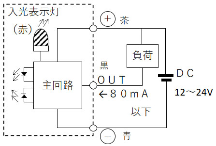 |
||
| 電源・電圧 | DC12-24V±10% リップル(p-p)5%以下 | ||
| 接続方式 | EE-1010 2M付き | ||
| 上減速・上限停止 | ||||
|---|---|---|---|---|
| メーカ | オムロン(株) | |||
| フォト・マイクロセンサ | EE-SX672-WR | |||
| 入出力段 回路図 |
タイム チャート |
入光時ON | 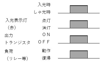 |
接続端子 |
 |
||||
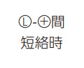
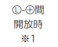
| しゃ光時ON |
推奨  |
接続端子 | ||
 |
||||
| 出力回路 |  |
|||
| 電源・電圧 | DC5-24V±10% リップル(p-p) 10%以下 | |||
| 接続方式 | コード引き出しタイプ | |||
※1 しゃ光時ONの際にL端子を0Vと短絡しないでください。
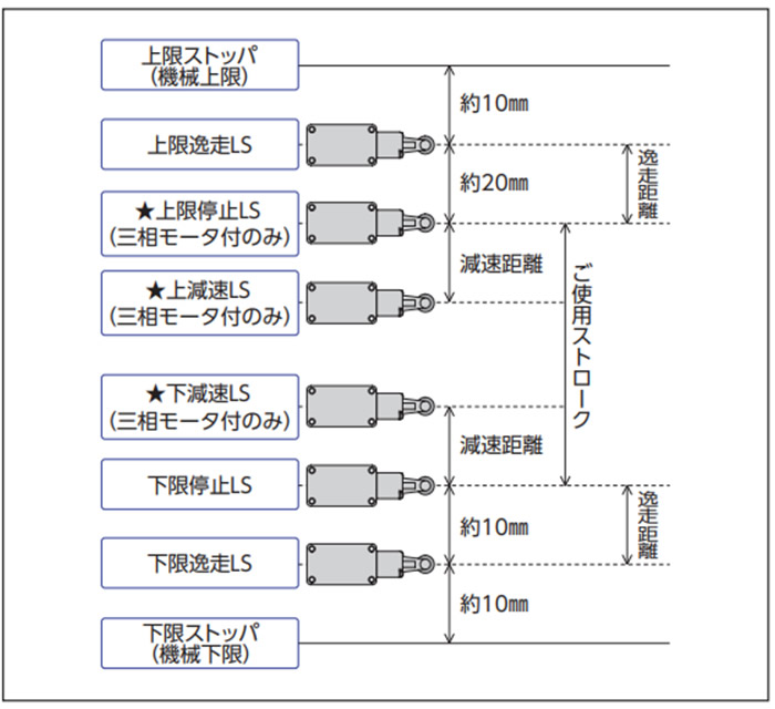
リミットスイッチ(LS)の配置(ZSL1000)
リミットスイッチ(LS)の配置(ZSL0050)

| 上限逸走・下限逸走 | ストローク調整用リミットスイッチ | |
|---|---|---|
| メーカ | オムロン(株) | |
| 小型スイッチ | D2VW-5L1-1M | |
| 接触仕様 | 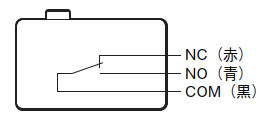 |
|
| 定格電圧 | AC250V | 抵抗負荷:5A |
| AC125V | 抵抗負荷:5A | |
| DC30V | 抵抗負荷:5A | |
リミットスイッチの配置図の★印のセンサは、三相モータ付の場合のみ。 (サーボモータ付及びエンコーダ付モータの場合はこの位置のセンサはありません) 詳細は、納入図をご参照ください。
- ・ストロークの上下限は、上下停止リミットスイッチ(LS)で設定します。上下停止LSが有効に動作しない場合に備えて、上下限逸走LSを設けてあります。
- ・上下限逸走センサが動作した場合は、リフタを急制動で停止できるように直流別切りのブレーキ回路、およびシーケンス回路を外部で組み込んでください。
(リフタを最高速度以上で昇降させたり、ブレーキを交流切りにすると、リフタがストッパに衝突するため、絶対に避けてください。[ブレーキ制動時の遅れ時間が発生し、制動距離が伸びるため]
また、上限ストッパ、下限ストッパは機械的上限・下限で設定しています。絶対にさわらないでください。緩んでいたり、途中で止まっていると、天板フレームが下降時に接触し、機器の破損や重大な事故につながる恐れがあります。 - ※リフタ運転時の中間停止が必要な場合はロータリエンコーダ付き、もしくはサーボモータ付きをご使用ください。
