技術資料 高速リフタ リフトマスタ 選定
検討時の注意点
1. 加減速時間について
- ・リフトマスタは昇降速度が速いため、三相モータ付の場合は、インバータ制御を必須とし、十分な加減速時間を設けてご使用ください。
また、サーボモータ付の場合も十分な加減速時間を設けてご使用ください。
急加速・急停止しますと停止精度の悪化やワークの振動が発生する場合があります。
据付面・アームの剛性や荷重条件により、起動停止時にリフトマスタが振れる場合は加減速時間を長く取ってご使用ください。
また、振れ量を軽減させる場合はリフトマスタ上部の固定をご検討ください。 - ・標準機種一覧(ボールネジタイプ・台形ネジタイプ)に示す“速度”は最大速度です。
昇降時間を求める場合は加減速時間を含めて計算してください。 - ・さらなる昇降時間の短縮・高頻度運転・多点位置決め・連動運転などが必要な場合はサーボモータ付をお奨めします。
2. インバータ制御について
- ・下降時には大きな回生電流が発生しますので、ご使用条件にもとづき十分なインバータ回生抵抗器の容量を設けてください。回生抵抗器の容量についてはインバータメーカへご相談願います。
- ・インバータはモータに対して1枠大きい容量のご使用を推奨します。
- ・インバータトリップ時にはブレーキが作動するシーケンスを組んでください。
3. 落下防止について
- ・リフトマスタは無励磁作動形ブレーキ付モータを採用しています。サーボモータ付としてお客様にてモータをご用意される場合はブレーキ付キー溝軸仕様をご採用ください。
また、万が一の落下に備えお客様にて落下防止機構をご用意ください。また、当社でも落下防止用ピンを特形対応として製作可能です。
4. サーボモータ制御について
- ・サーボモータは定格回転速度以下でご使用願います。
- ・下降時に大きな回生電流が発生します。条件に応じて十分な回生抵抗器を設けてください。
- ・緊急時に停止させる場合であっても、モータ内蔵のメカブレーキによる制動はしないでください。必ず、ダイナミックブレーキによる減速後にメカブレーキが作動するような制御ロジックとしてください。詳細は、モータメーカの取扱説明書をご参照ください。
選定について
選定に必要な使用条件
- 1. 使用装置と必要台数
- 2. 昇降物質量
- 3. 速度
- 4. ストローク
- 5. 負荷のオーバハング量
- 6. 使用頻度
- 7. 使用環境
選定手順
- 1. 使用機械、使用方法、使用環境がリフトマスタに適しているか確認します。
- 2. 昇降荷重を満足する定格荷重を持つ形番を標準機種一覧(ボールネジタイプ・台形ネジタイプ)より選択します。
※定格荷重を超える昇降荷重の場合は複数連動運転をご検討ください。
複数連動運転の選定・制御方法はご相談ください。また、高負荷仕様も特形として対応しますのでご相談ください。 - 3. 昇降速度は選択形番の称呼速度で満足するか確認します。
※昇降速度を上げた仕様も対応しますのでご相談ください。 - 4.必要なストロークを確認します。
※ストローク1.5mを超える場合は特形として対応しますのでご相談ください。 - 5. 選定形番の許容オーバハングロードが満足するか下記を参照に確認します。
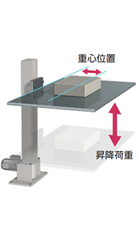
許容オーバハングロード(OHL)の確認
昇降荷重と重心位置を確認すれば、簡単にリフトマスタが選定できます。右図のように、昇降荷重と重心位置の交点が許容オーバハングロード値となります。
各形番毎のオーバハングロード荷重曲線(ボールネジタイプ・台形ネジタイプ)をご覧ください。
注意
- ・アームに荷重が掛かると、リフトマスタは荷重方向に歪み、アーム先端が水平より下がることを見込むことが必要です。歪み量はリフトマスタのストロークが長いほど大きくなるだけでなく、アーム・据付面の剛性にも影響します。
- ・歪み量や起動停止時の振れ量を軽減させる場合はリフトマスタ上部の固定をご検討ください。
- ・リフトマスタの歪み量についての詳細は別途お問合せください。
LMEB1000
(ワーク取付面基準:外形図参照)
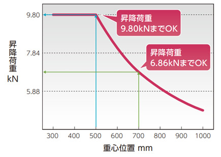
LMEB1000の場合
例1 重心位置が500mmの時、昇降は荷重9.80kNまで可能です。
例2 重心位置が700mmの時、昇降は荷重6.86kNまで可能です。
