技術資料 機械式過負荷保護機器 取扱
トルクリミター TL 取扱
トルクの設定
トルクリミターのスリップトルクの設定は、調節ナットまたはボルトの締付調整により行います。
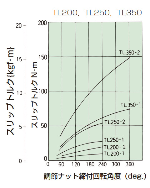
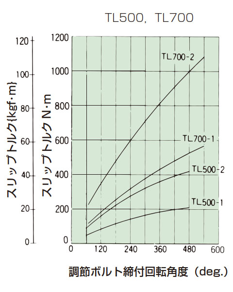
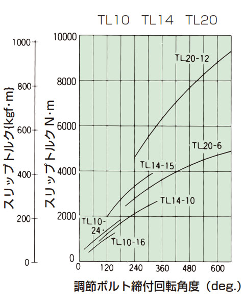
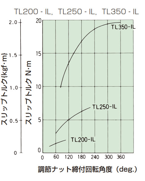
- (1)トルクリミターを機械に取付けた後、調節ナットまたは調節ボルトをゆるく締付けた状態から、順次大きな締付量へと数回試運転を行い、もっとも適した締付位置を見つけてください。なお、締付量-トルク相関図(下表)より、調節ナット、調節ボルトの一定締付量に対するスリップトルクの値を読み取っていただくこともできます。しかし摩擦面の状態その他により、一定締付量に対するトルクは変化します。グラフはあくまで目安として少しゆるめの締付量で試運転を行い、その機械にあった締付量を見つけ出すのが、もっとも実際に即した方法です。スリップトルクの安定性が特に必要な場合には、調節ナットまたはボルトを手でいっぱい締付けた後、さらに60度スパナで締込んだ状態で約500回転スリップさせて摩擦面の慣らしを行ってください。回転速度が速い場合は数回に分けて500回転スリップさせてください。
- (2)センタメンバを組込んだ状態で、ご指定のトルクに設定してお納めすることもできます。その場合は軸穴加工済みであることが必要です。
締付量-トルク相関図
調節ナットまたは調節ボルトを手で締付けて、皿バネを固定した状態を0ポイントとします。
[クリックで拡大]
[クリックで拡大]
[クリックで拡大]
[クリックで拡大]

[クリックで拡大]
センタメンバの選定・製作
トルクリミターには、センタメンバとしてスプロケット・ギヤをはさみ込むことができます。
これらセンタメンバを貴社にて選定・製作される場合には、下記の点にご注意ください。
- (1)トルクリミター外径(D)により、センタメンバの最小径が制限されますので確認してください。
チェーン伝動でスプロケットを使用する場合の最小歯数は、下記センタメンバ用スプロケット表をご参照ください。 - (2)センタメンバの摩擦面(両側)は、3S~6Sに仕上げてください。
- (3)センタメンバの穴径は、寸法表のセンタメンバ穴径の寸法公差通りで3S~6Sに仕上げてください。
- (4)センタメンバが、はさみ込まれる部分の厚みは寸法表のS寸法以内にしてください。
トルクリミター動作の検出について
トルクリミターは過負荷時にスリップして機械を保護しますが、駆動源を停止させないと、トルクリミターはスリップし続けます。スリップを続けますと摩擦板が異常摩耗したり異常発熱することがあり、すぐに駆動源を停止させる必要があります。
トルクリミターがスリップしたことを検出し駆動源を停止させるための一例として近接スイッチとデジタルタコメータによる以下のような方法がありますので紹介します。
取付例
形式1
被動機械に過負荷がかかって、トルクリミターのセンタメンバが停止する場合
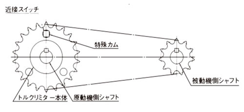
形式2
被動機械に過負荷がかかって、トルクリミター本体が停止する場合
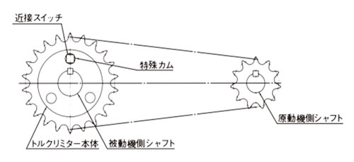
形式3
トルクリミターをカップリングするタイプで使用し、過負荷のときセンタメンバ側が停止する場合

形式4
トルクリミターをカップリングタイプで使用し過負荷のとき本体側が停止する場合
形式4の取付方法は、特殊カムの取付けが困難ですのでできるだけ避けてください。カップリングタイプでトルクリミターを使用するときには、形式3を採用してください。
下表のように特殊カムの個数を選ぶと検出回転速度において約1秒から10秒でスリップを検出することができます。
特殊カム個数と検出回転速度
| 特殊カム個数 | 検出回転速度範囲 r/min |
|---|---|
| 1 | 6~60 |
| 2 | 3~30 |
| 3 | 2~20 |
| 4 | 1.5~15 |
| 5 | 1.2~12 |
| 6 | 1.0~10 |
| 7 | 0.85~8.5 |
| 8 | 0.75~7.5 |
| 9 | 0.67~6.7 |
| 10 | 0.6~6.0 |
参考接続図
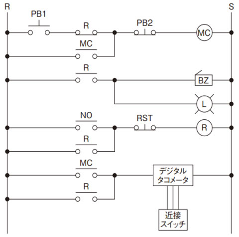
- PB1:モータ運転押釦
- PB2:モータ停止押釦
- RST:BZ、L リセット押釦
- MC:モータ用電磁接触器
- R:補助リレー
- NO:デジタルタコメータ出力 a 接点
- BZ:ブザー
- L:ランプ
デジタルタコメータ:オムロン(株)製 H7CX-R11-N
近接スイッチ:オムロン(株)製 TL-N5ME2
注) デジタルタコメータと近接スイッチは上記オムロン(株)製をおすすめします。
詳しくはオムロン(株)発行のカタログをご覧ください。
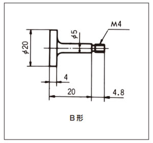
特殊カムの寸法と取付け
特殊カムは従動側にネジ止めします。
ゆるみ止めにはネジロックなどをご使用ください。
特殊カム参考図
※お客様にてご用意ください。
センタメンバ用スプロケット
センタメンバとしてスプロケットをご使用になる際は以下の点にご注意ください。
下表はセンタメンバとしてスプロケットを使い、チェーン伝動をする場合です。
- (1)取付形式 1、2 を採用する場合でチェーンが特殊カム(参考図通りの場合)に当たらない最小歯数
- (2)トルクリミター単体でチェーンが摩擦板に当たらない最小歯数
- (3)ブシュの長さ
- (4)スプロケット穴径(センタメンバ穴径)
| 形番 | スプロケット 穴径 (センタメンバ 穴径) |
使用スプロケット最小歯数 | ||||||||||||||||||
|---|---|---|---|---|---|---|---|---|---|---|---|---|---|---|---|---|---|---|---|---|
| RS35 | RS40 | RS50 | RS60 | RS80 | RS100 | RS120 | RS140 | RS160 | ||||||||||||
| 最小 歯数 |
ブシュ 長さ |
最小 歯数 |
ブシュ 長さ |
最小 歯数 |
ブシュ 長さ |
最小 歯数 |
ブシュ 長さ |
最小 歯数 |
ブシュ 長さ |
最小 歯数 |
ブシュ 長さ |
最小 歯数 |
ブシュ 長さ |
最小 歯数 |
ブシュ 長さ |
最小 歯数 |
ブシュ 長さ |
|||
| TL200 | 30+0.03 0 |
△20 | 3.8 | 16 | 6 | - | - | - | - | - | - | - | - | - | - | - | - | - | - | |
| TL250 | 41+0.05 0 |
- | - | 20 | 6.5 | 17 | 6.5 | - | - | - | - | - | - | - | - | - | - | - | - | |
| TL350 | 49+0.05 0 |
- | - | 26 | 6.5 | 21 | 6.5 | 18 | 9.5 | 15 | 9.5 | - | - | - | - | - | - | - | - | |
| TL500 | 74+0.05 0 |
- | - | - | - | △29 (30) |
6.5 | 25 | 9.5 | 19 | 9.5 | - | - | - | - | - | - | - | - | |
| TL700 | 105+0.05 0 |
- | - | - | - | - | - | △33 (35) |
9.5 | 26 | 12.5 | 21 | 12.5 | 18 | 12.5 | - | - | - | - | |
| TL10 | 135+0.07 0 |
- | - | - | - | - | - | - | - | - | - | △29 (30) |
12.5 | 24 | 15.5 | △22 | 19.5 | - | - | |
| TL14 | 183+0.07 0 |
- | - | - | - | - | - | - | - | - | - | △39 (40) |
15.5 | △33 (35) |
15.5 | △29 | 19.5 | △26 | 23.5 | |
| TL20 | 226+0.07 0 |
- | - | - | - | - | - | - | - | - | - | △54 | 15.5 | △46 (60) |
15.5 | △40 | 19.5 | △35 | 23.5 | |
- 注) 1. △印はA形標準スプロケットではありません。標準在庫スプロケットをご使用の場合は()内の歯数をご使用ください。
- 注) 2. ブシュ長さは参考です。
| 形番 | スプロケット 穴径 (センタメンバ 穴径) |
使用スプロケット最小歯数 | ||||||||||||||||||
|---|---|---|---|---|---|---|---|---|---|---|---|---|---|---|---|---|---|---|---|---|
| RS35 | RS40 | RS50 | RS60 | RS80 | RS100 | RS120 | RS140 | RS160 | ||||||||||||
| 最小 歯数 |
ブシュ 長さ |
最小 歯数 |
ブシュ 長さ |
最小 歯数 |
ブシュ 長さ |
最小 歯数 |
ブシュ 長さ |
最小 歯数 |
ブシュ 長さ |
最小 歯数 |
ブシュ 長さ |
最小 歯数 |
ブシュ 長さ |
最小 歯数 |
ブシュ 長さ |
最小 歯数 |
ブシュ 長さ |
|||
| TL200 | 30+0.03 0 |
△25 | 3.8 | 19 | 6 | - | - | - | - | - | - | - | - | - | - | - | - | - | - | |
| TL250 | 41+0.05 0 |
- | - | 24 | 6.5 | 20 | 6.5 | - | - | - | - | - | - | - | - | - | - | - | - | |
| TL350 | 49+0.05 0 |
- | - | 30 | 6.5 | 24 | 6.5 | 21 | 9.5 | 17 | 9.5 | - | - | - | - | - | - | - | - | |
| TL500 | 74+0.05 0 |
- | - | - | - | 32 | 6.5 | △28 (30) |
9.5 | 21 | 9.5 | - | - | - | - | - | - | - | - | |
| TL700 | 105+0.05 0 |
- | - | - | - | - | - | 36 | 9.5 | △28 (30) |
9.5 | △23 (24) |
12.5 | 20 | 12.5 | - | - | - | - | |
| TL10 | 135+0.07 0 |
- | - | - | - | - | - | - | - | - | - | △31 (32) |
12.5 | 26 | 15.5 | △23 | 19.5 | - | - | |
| TL14 | 183+0.07 0 |
- | - | - | - | - | - | - | - | - | - | △41 (45) |
15.5 | 35 | 15.5 | △30 | 19.5 | △27 | 23.5 | |
| TL20 | 226+0.07 0 |
- | - | - | - | - | - | - | - | - | - | △56 (60) |
15.5 | △47 (60) |
15.5 | △41 | 19.5 | △36 | 23.5 | |
- 注) 1. △印はA形標準スプロケットではありません。標準在庫スプロケットをご使用の場合は()内の歯数をご使用ください。
- 注) 2. ブシュ長さは参考です。
