技術資料 機械式過負荷保護機器 選定
選定手順や注意事項等をご覧になりたい方は下記へお進みください。
製品シリーズの絞り込みや仮選定をご希望の方は
こちらをクリックしてください。
トルクキーパー TFK 選定
トルクキーパーを人員輸送装置や昇降装置にご使用される場合は人的災害や落下事故が発生しないような措置を装置側で講じてください。
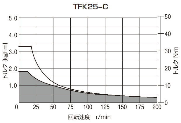
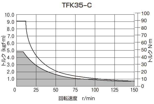
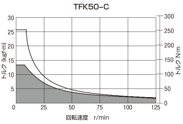
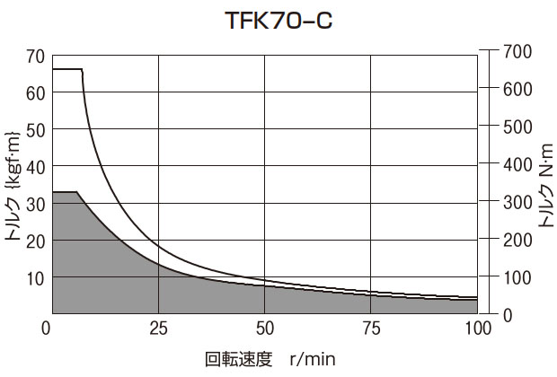
- 1. 使用目的に応じて、下表の使用条件を決め、ページ末のT-N曲線図よりサイズを決定します。
使用目的 使用条件 サイズの決定 アキュムレーション 各コンベヤのトルクキーパーの、下記の項目を決めます。 - (1) スリップトルク
- (2) スリップ回転速度
- (3) スリップ時間(コンベヤの停止時間)
- (4) 連結時間(コンベヤの駆動時間)
- (5) 1日の使用時間
スリップトルクおよびスリップ回転速度が、T-N曲線図の許容値以内(曲線の下)になるようにサイズを決めてください。
スリップ時間が連結時間より長い場合や、1日の使用時間が8時間を越える使用条件では、T-N曲線図の 部以内でのご使用をお奨めします。
ブレーキング 各機械装置のトルクキーパーの、下記の項目を決めます。 - (1) ブレーキトルク
- (2) 回転速度
- (3) スリップ時間(ブレーキの作用時間)
- (4) 連結時間(ブレーキの作用しない時間)
- (5) 1日の使用時間
ただし、連続スリップの場合は(3)、(4)は不要です。
ブレーキトルクおよび回転速度が、T-N曲線図の許容値以内(曲線の下)になるようにサイズを決めてください。
スリップ時間が連結時間より長い場合や、1日の使用時間が8時間を越える使用条件では、T-N曲線図の 部以内でのご使用をお奨めします。
ドラッギング 各機械装置のトルクキーパーの、下記の項目を決めます。 - (1) スリップトルク
- (2) スリップ回転速度
- (3) スリップ時間
- (4) 連結時間
- (5) 1日の使用時間
スリップトルクおよびスリップ回転速度が、T-N曲線図の許容値以内(曲線の下)になるようにサイズを決めてください。
スリップ時間が連結時間より長い場合や、1日の使用時間が8時間を越える使用条件では、T-N曲線図の 部以内でのご使用をお奨めします。
- 2. 決定したトルクキーパーの軸穴範囲が取付ける軸径を満足するか確認します。
- 3. スリップトルクの設定
トルクキーパーは各形番とも設定トルク範囲(製品ページ参照)の最大の50%の値でトルク設定を行い、そのトルクカーブを添付して出荷しています。
この50%トルクを0ポイントといい、スリップトルクの設定は、この0ポイントを基準にして行います。
詳しくは取扱2の項(こちら参照)をご参照ください。
選定上の留意点
- 1. マサツ面に水・油脂などが浸入するとトルクが低下し、安定したスリップトルクが得られませんので、ご注意ください。
- 2. T-N曲線図は周囲温度40℃以下の範囲に適用します。これを超える場合は当社までご連絡ください。
- 3. 使用する軸径に対してスリップトルクがトルクキーパーの設定トルク範囲より小さい場合は、当社までご連絡ください。
- 4. 使用回転方向を逆転させた場合、バックラッシが生じます。使用上、バックラッシが発生してはいけない装置では、ご使用できません。
T-N曲線図 { }は参考値です。
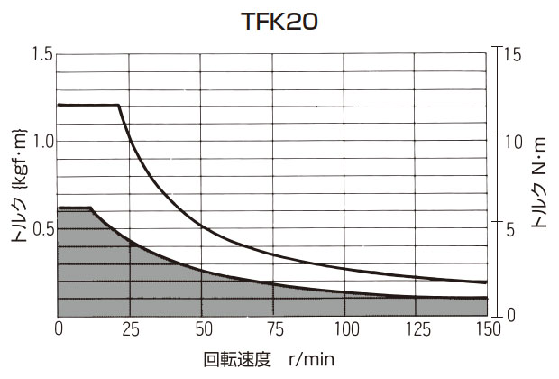
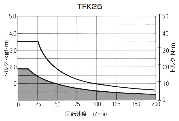
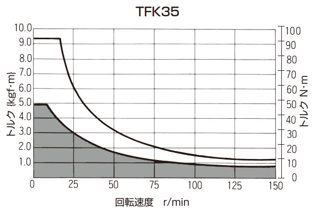
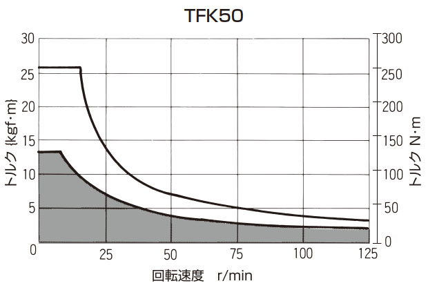
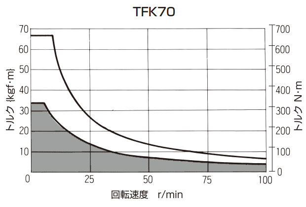
注)T-N曲線図はトルクキーパーの許容温度を基準にしています。
より安定したスリップトルクが必要な場合は 部以内の条件での使用をお奨めします。
ただし、回転速度が30r/min以下の場合スティックスリップ現象が発生し、トルクが安定しない場合がありますのでご注意ください。
スティックスリップ現象とは、摩擦面が止まったり、すべったりを繰返す現象です。