技術資料 カップリング 取扱
エクトフレックスカップリング NERシリーズ 取扱
エクトフレックスカップリングNERシリーズに関する一般取扱いについて記載しています。詳細につきましては、製品に添付しています取扱説明書をご参照ください。
1. ハブの軸への取付け
注意事項
- ※1 カップリングの構成部品を、取扱説明書の構成部品リストと照合してください。
- ※2 センタユニットは工場で最適に組立てています。分解せずにそのままご使用ください。
- ※3 センタユニットには、特に軸方向に大きな力が作用しないようにしてください。ディスクが撓んだ状態で固定されてしまい、性能を損なう恐れがあります。
取付手順
- (1) 駆動軸・被動軸・ハブ内径にカエリ、傷、汚れ、錆等がないか確認し、ゴミや油分を拭きとってください。
- (2) 各々の軸にハブを取付けてください。しまりばめの場合は加熱油(150℃以下)でハブを均一に加熱し、軸上の所定の位置に素早く取付けてください。
- (3) ハブのフランジ面間寸法は、次項「2.心出し(1)フランジ面間寸法(J)の調整」を参照してください。
2. 心出し
カップリングの最初の心出し精度が高ければ高いほど、使用中に発生する偏心回転応力を抑えることができます。
軸受の摩耗、据付面の沈下、温度による状態変化、振動等による使用中の変化が、お客様の機器とカップリングの寿命を短くすることになります。
定期的に、以下の手順に従って調整を行ってください。
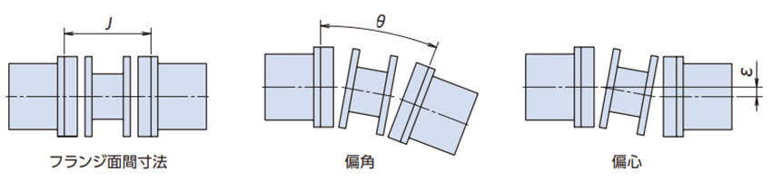
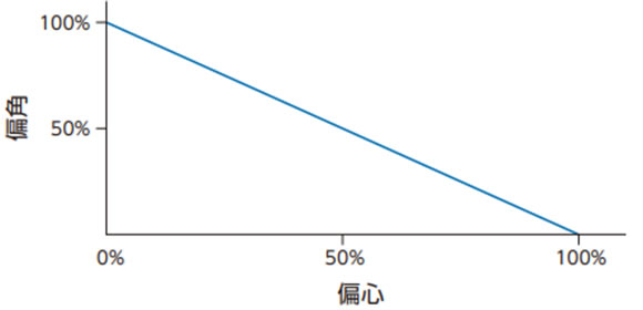
カップリングのフランジ面間寸法誤差、許容偏角、偏心は相関関係にあり、一方が増加すると一方が減ずるため同時に考慮する必要があります。
下記の推奨値以下に最初に心出しを確実に行ってください。
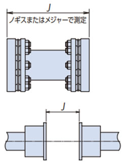
(1) フランジ面間寸法(J)の調整
センタユニットの全長を測定し、その値をJ寸法としてください。
(部品公差の組合せ具合によって、センタユニットの全長が基準値よりも長くなったり短くなったりすることがあります。その場合、図面基準寸法にてJ±0.5mm以内にハブをセットしてもセンタユニットが組込みにくいことがあります。)
J寸法を90度毎に4ヵ所測定し、その平均値がJ±0.5mm以内となるようハブの位置を調整してください。駆動軸、被動軸が段付きシャフトの場合は、調整代が制限される場合がありますのであらかじめJ寸法が調整可能なように配慮ください。
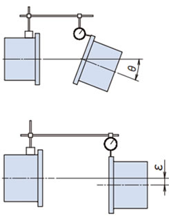
(2) 偏角(θ)の調整
- (a)図のようにダイヤルゲージを片側ハブに固定し、そのハブを回転させダイヤルゲージの最小読みを見つけ、ゼロにセットしてください。
- (b)ダイヤル側のハブを360度回転させ、偏角の数値を読み取ってください。
- (c)ダイヤルゲージの読みが表1の偏角推奨値の範囲に入るように機器をシム等で移動させて調整してください。
(3) 偏心(ε)の調整
- (a)図のようにハブフランジにダイヤルゲージを取付け、そのハブを回転させてダイヤルゲージの最小読みを見つけ、ゼロにセットしてください。
- (b)ダイヤルゲージで固定している側のハブを360度回転させ、偏心の数値を読み取ってください。
- (c)ハブの外周部のフレが、ハブのキリ穴部分で、異常にフレる場合があります。これは、キリ穴部分を加工する際、フランジが外周方向にふくらんだためですので、その部分を避けて読み取ってください。
- (d)ダイヤルゲージの読みが表1または表2の偏心推奨値の2倍以内の範囲に入るように機器をシム等で移動させて調整してください。
- (e)偏心の調整のため、機器を移動させた場合には、再度、偏角の調整を行ってください。
| 形番 | 心出し推奨値 | ||||
|---|---|---|---|---|---|
| 偏角 | 偏心 ε[mm] |
フランジ 面間寸法 J[mm] |
|||
| θ [deg] |
T.I.R. [mm] |
||||
| NER59W | 0.35 | 0.33 | 0.18 | ±0.5 | |
| NER93W | 0.35 | 0.39 | 0.22 | ±0.5 | |
| NER230W | 0.25 | 0.31 | 0.18 | ±0.5 | |
| NER360W | 0.25 | 0.36 | 0.22 | ±0.5 | |
| NER630W | 0.25 | 0.43 | 0.22 | ±0.5 | |
| NER850W | 0.25 | 0.48 | 0.25 | ±0.5 | |
| 形番 | 心出し推奨値 | ||||
|---|---|---|---|---|---|
| 偏角 | 偏心 (算出式) ε[mm] |
フランジ 面間寸法 J[mm] |
|||
| θ [deg] |
T.I.R. [mm] |
||||
| NER59W | 0.35 | 0.33 | (J-44.4)×0.31×10-2 | ±0.5 | |
| NER93W | 0.35 | 0.39 | (J-50.6)×0.31×10-2 | ±0.5 | |
| NER230W | 0.25 | 0.31 | (J-58.8)×0.22×10-2 | ±0.5 | |
| NER360W | 0.25 | 0.36 | (J-70.0)×0.22×10-2 | ±0.5 | |
| NER630W | 0.25 | 0.43 | (J-76.4)×0.22×10-2 | ±0.5 | |
| NER850W | 0.25 | 0.48 | (J-86.6)×0.22×10-2 | ±0.5 | |
偏角と偏心の関係
3. センタユニット取付け
- (1) 取扱説明書の構成部品図を参照の上、センタユニットをハブに取付けてください。

図1.センタユニットの取付け
ハブ外周とセンタユニット外周の各2カ所(片側)に合マーク(線)があります。
これらが一致する位相としてください。
センタユニットに方向性はありませんので、左右どちら向きでも取付け可能です。
- (2) 位置決めボルトおよび六角穴付ボルトにて、ハブとセンタユニットを固定します。
この時、位置決めボルト(頭部が緑色のボルト)は合マーク(線)部のキリ穴に挿入するようにしてください。他のキリ穴には入りません。
位置決めボルト(頭部が緑色のボルト)は、片側で180°対称に2ヵ所使用します。 (カップリング1台で4ヵ所)
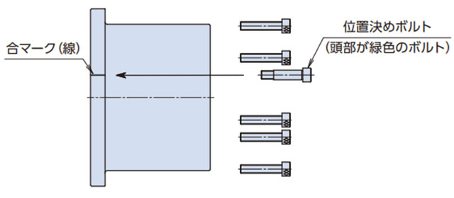
図2.位置決めボルトおよび六角穴付ボルトの挿入
位置決めボルトおよび六角穴付ボルトは、必ず、表3の『位置決めボルトおよび六角穴付ボルトの締付トルク』で締込んでください。
表3.位置決めボルトおよび六角穴付ボルトの締付トルク 形番 ボルトサイズ 締付トルク
[N・m]NER59W M6 14 NER93W M6 14 NER230W M6 14 NER360W M8 34 NER630W M10 67 NER850W M10 67 - (3) 組立てができましたら、ディスク部にあるディスク保護板を取外してください。
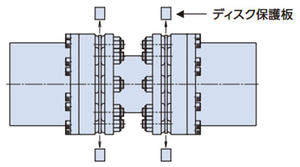
ディスク保護板は、片側に2個、合計4個取付けてあります。
4. 点検
実際の運転に入って1~2時間後に、偏角と偏心を再チェックしてください。
その際、位置決めボルトおよび六角穴付ボルトを表3の規定のトルクで再締付けしてください。
また、半年~1年毎に部品の異常や位置決めボルトおよび六角穴付ボルトのゆるみがないことを確認してください。
ゆるみのチェックのために据付け後、位置決めボルトおよび六角穴付ボルトとハブへマーキングを入れておくことを推奨します。
その他の部品にも異常がないかチェックしてください。
