技術資料 カップリング 取扱
ローラチェーンカップリング 取扱
-
1. オイルシールを左右いずれかのスプロケットに、シールのリップ方向が歯部側になるようにはめておきます。
(垂直取付の場合は、上側のスプロケットにオイルシールを取付けてください。)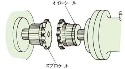
-
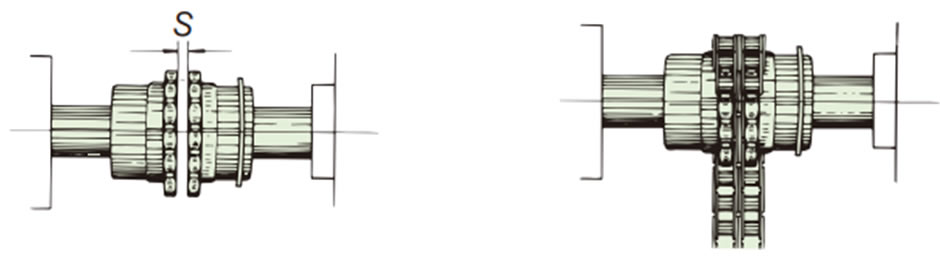
2. スプロケットの側面を密着させ、偏角(角度誤差)、偏心(平行誤差)を修正します。
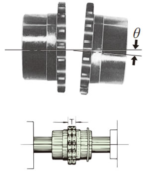
歯の側面の長さTが外周で等しくなるように角度を修正します。
許容偏角(角度誤差) θ = 1°以下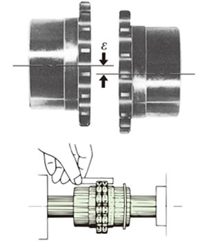
歯底にストレートなものを当て、歯底の食い違いがないようにします。
許容偏心(平行誤差) ε = チェーンピッチの2%以下(下表の値を参照ください)伝動能力表の最高回転速度の1/3以上の回転で使用する場合の取付許容誤差はθ = 0.5°以下、ε = チェーンピッチの1%以下にしてください。
- 3. 両スプロケットの間をS寸法(寸法表参照)にして、スプロケットをセットスクリューで固定します。
-
4. グリースを両スプロケット間のS寸法部につめ、歯部にも塗布します。
次いでチェーンにグリースを塗布しスプロケットに巻き付け、継手ピンにて止めます。継手ピンはオイルシール側より差し込み、反オイルシール側にクリップもしくは割ピンが来るようにセットし、確実に取付けられている事を確認します。
-
5. ケースを使用する場合は、ケース両側にグリースを所要量入れ、ボルトで両側のケースをスプロケットにしっかりと取付けます。
運転当初わずかなグリースの漏れがありますが、間もなく安定します。漏れが止まらない場合は、取付けに問題がないかを確認ください。
| 形番 | CR3812 | CR4012 | CR4014 | CR4016 | CR5014 | CR5016 | CR5018 | CR6018 | CR6022 |
|---|---|---|---|---|---|---|---|---|---|
| 許容偏心 (平行誤差) (ε) mm | 0.19 | 0.254 | 0.254 | 0.254 | 0.318 | 0.318 | 0.318 | 0.381 | 0.381 |
| 許容偏角 (角度誤差) (θ)° | 1 | 1 | 1 | 1 | 1 | 1 | 1 | 1 | 1 |
| 許容エンドプレイ (軸方向変位) mm | S±0.31 | S±0.68 | S±0.68 | S±0.68 | S±0.88 | S±0.88 | S±0.88 | S±1.02 | S±1.02 |
| 形番 | CR8018 | CR8022 | CR10020 | CR12018 | CR12022 | CR16018 | CR16022 | CR20018 | CR20022 |
|---|---|---|---|---|---|---|---|---|---|
| 許容偏心 (平行誤差) (ε) mm | 0.508 | 0.508 | 0.635 | 0.762 | 0.762 | 1.016 | 1.016 | 1.270 | 1.270 |
| 許容偏角 (角度誤差) (θ)° | 1 | 1 | 1 | 1 | 1 | 1 | 1 | 1 | 1 |
| 許容エンドプレイ (軸方向変位) mm | S±1.32 | S±1.32 | S±1.52 | S±2.02 | S±2.02 | S±2.52 | S±2.52 | S+1.0/-3.0 | S+1.0/-3.0 |
- 注)1. 各許容誤差は、他の誤差がゼロとした場合です。
- 注)2. 伝動能力表の最高回転速度の1/3以上の回転で使用する場合の取付許容誤差はθ = 0.5°以下、ε = チェーンピッチの1%以下にしてください。
使用上の注意
- 1. 高速回転や激しい振動のある用途では、必ずボルトにゆるみ止め剤を塗布してからケースを取り付けてください。
- 2. ボルトの緩みやケースの破損、チェーンの切断など、万一に備えて固定カバーを設置してください。
- 3. 据付、点検時にチェーンを外す際には、装置負荷側がフリーになることで危険な状態にならない事を確認してから作業を開始してください。
- 4. グリース漏れが許されないような雰囲気でご使用される場合は当社へご相談ください。
- 5. 据付、点検の際には必ず事前に取扱説明内容を確認の上作業してください。
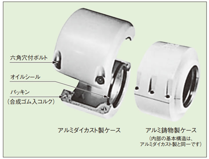
ケースの構造と役割
ケースは取付け、点検に便利なように、軸と直角方向に分離できる割形になっており、ボスとの嵌合部はボスをしっかりと保持し、しかも偏心のないように精密に仕上げられています。
また、他方の穴は台形溝になっており、これにオイルシールを入れて油漏れを防ぐとともに、カップリングのフレキシビリティをそこなわないよう、スプロケットのボスを自由に保持します。
割形の接合部は、パッキンをはさんで油密にし、ボルトで止めています。
チェーンカップリングにケースを付けると、潤滑剤の飛散と塵埃の侵入を防ぎ潤滑が完全になりますので、カップリングの寿命を著しく長くします。また、腐蝕性雰囲気に対して本体を保護するとともに、危険を防止し、外観も美しくなります。
特に起動・停止頻度が多い場合や振動が大きい場合で、ケースを取付ける時にはご相談ください。
次の場合には必ずケースを付けてください。
- (1) 高い回転速度で使う場合。(伝動能力表注参照)
- (2) 塵埃などの摩耗性雰囲気内で使う場合。
- (3) 湿気などの腐蝕性雰囲気内で使う場合。