技術資料 カップリング 選定と手順
選定手順や注意事項等をご覧になりたい方は下記へお進みください。
製品シリーズの絞り込みや仮選定をご希望の方は
こちらをクリックしてください。
使用条件が決まっており詳細な選定をご希望の方は
こちらをクリックしてください。
エクトフレックスカップリング NEF・NEHシリーズ 選定
1.補正トルクの計算
1-1. サーボモータ、ステッピングモータとの連結の場合
サーボモータ、ステッピングモータの最大トルクに対して、負荷の種類に応じて下表の使用係数(SF)を乗じ、補正トルクを求めます。
| 負荷の種類 | 一様な負荷 | 中程度の変動負荷 | 激しい変動負荷 |
|---|---|---|---|
| 使用係数(SF) | 1.2 | 1.4 | 1.5 |
1-2. 汎用電動機等との連結の場合
以下の計算式で求めた負荷トルクに対し、負荷の種類に応じて右表の使用係数(SF)を乗じ、補正トルクを求めます。
T = 9550 × P n
- T' = T × SF
- T = 負荷トルク N・m
- P = 伝達動力 kW
- n = 回転速度 r/min
- T' = 補正トルク N・m
| 負荷の種類 | 原動機の種類 | ||||
|---|---|---|---|---|---|
| 汎用電動機、ガスタービン | エンジン | ||||
| 慣性 モーメントが 小さい場合 |
慣性 モーメントが 大きい場合 |
4気筒 | 6気筒 | 8気筒 | |
| 一様な負荷 | 1.5~1.75 | 1.75~2.0 | 2.5~4.0 | 2.0~2.5 | 1.5~2.0 |
| 中程度の変動負荷 | 2.0~2.5 | 2.5~3.0 | 4.0~5.0 | 2.5~3.5 | 2.0~3.0 |
| 激しい変動負荷 | 3.0~4.5 | 4.5~6.0 | 4.5~5.5 | 3.0~4.0 | 2.5~3.5 |
- ※衝撃負荷がかかる場合は、原動機が出しうる最大トルクに対し、1~2.5の衝撃係数を乗じ、補正トルクとしてください。
- * 軸締結方法がクランプ取付・パワーロック取付の場合、起動トルクを含め瞬時でも軸穴の摩擦伝達トルク(各製品ページ参照)を超えるトルクが掛からないようにしてください。
2.軸径
取付軸がカップリングの取付可能軸径範囲に入っていることを確認してください。
パワーロック付の場合は、パワーロックのサイズ、個数、伝達トルクも確認してください。
クランプタイプの場合、1で計算した補正トルクがクランプの伝達トルク以内であることを確認してください。
なお、中空軸に取付ける場合は強度確認が必要ですので、当社までお問合せください。
3.形番選定
前項1~2を満足するエクトフレックスカップリングを、伝動能力表から選んでください。
注.ロングスペーサタイプの回転限界
ロングスペーサタイプを高速で使用される時、共振点を避けるため、回転速度をチェックする必要があります。
ロングスペーサタイプを選定される時、各形番におけるJ寸法、回転速度が限界内にあるかチェックしてください。
使用回転速度が記載の数値を超えるときは形番をあげて選定する必要があります。
| 形番 | 使用回転速度 [r/min] | ||||||||||||||
|---|---|---|---|---|---|---|---|---|---|---|---|---|---|---|---|
| 3600 | 2000 | 1800 | 1500 | 1200 | 1000 | 900 | 750 | 720 | 600 | 500 | 400 | 300 | 200 | 150 | |
| NEF04W | 980 | 1310 | 1380 | 1510 | 1680 | 1840 | 1940 | 2130 | 2170 | 2380 | 2610 | 2910 | 3360 | 4120 | 4750 |
| NEF10W | 1120 | 1500 | 1580 | 1730 | 1940 | 2120 | 2230 | 2450 | 2500 | 2730 | 2990 | 3350 | 3860 | 4730 | 5460 |
| NEF18W | 1180 | 1580 | 1660 | 1820 | 2040 | 2230 | 2350 | 2570 | 2620 | 2870 | 3150 | 3520 | 4060 | 4970 | 5740 |
| NEF25W | 1310 | 1760 | 1850 | 2030 | 2260 | 2480 | 2610 | 2860 | 2920 | 3190 | 3500 | 3910 | 4510 | 5520 | |
| NEF45W | 1440 | 1930 | 2030 | 2230 | 2490 | 2720 | 2870 | 3140 | 3210 | 3510 | 3840 | 4290 | 4960 | ||
| NEF80W | 1560 | 2090 | 2200 | 2410 | 2690 | 2950 | 3100 | 3400 | 3470 | 3800 | 4160 | 4650 | 5360 | ||
| NEF130W | 1780 | 3280 | 2510 | 2750 | 3070 | 3360 | 3540 | 3870 | 3950 | 4330 | 4740 | 5290 | |||
| NEF210W | 1890 | 2520 | 2660 | 2910 | 3250 | 3560 | 3750 | 4100 | 4190 | 4580 | 5020 | 5610 | |||
| NEF340W | 2024 | 2720 | 2870 | 3130 | 3500 | 3830 | 4040 | 4420 | 4510 | 4930 | 5400 | ||||
| NEF540W | 2180 | 2910 | 3070 | 3360 | 3750 | 4100 | 4320 | 4730 | 4820 | 5280 | 5780 | ||||
| NEF700W | 2270 | 3030 | 3190 | 3490 | 3890 | 4260 | 4490 | 4910 | 5010 | 5490 | |||||
| NEH09W | 2190 | 2930 | 3090 | 3380 | 3780 | 4130 | 4360 | 4770 | 4870 | 5330 | 5830 | ||||
| NEH14W | 2190 | 2930 | 3090 | 3380 | 3780 | 4130 | 4360 | 4770 | 4870 | 5330 | 5830 | ||||
| NEH20W | 2400 | 3200 | 3380 | 3690 | 4130 | 4520 | 4760 | 5210 | 5320 | 5820 | |||||
| NEH30W | 2570 | 3430 | 3610 | 3960 | 4420 | 4840 | 5100 | 5580 | 5690 | ||||||
| NEH41W | 2650 | 3540 | 3730 | 4080 | 4560 | 4990 | 5260 | 5760 | 5870 | ||||||
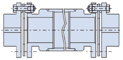
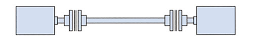
ロングスペーサ高速仕様
危険回転領域を避けるための対策としてカップリングのサイズアップがありますが、サイズアップできない場合は対策として右図のようにスペーサ質量を増やした仕様が製作可能です。
サーボモータ駆動における注意点
サーボモータによるボールネジ駆動システムにおいてはサーボモータの特性上、発振現象によりボールネジ駆動システム全体の固有振動数や電気制御状態によっては発振が増幅され大きな振動や異音が発生する事があります。
このような場合、駆動系システム全体のねじり剛性や慣性モーメントを調整し機械系のねじり固有振動数を上げるか、サーボモータの電気的制御のチューニング機能によりサーボゲインを調整することで回避してください。
動バランス調整
エクトフレックスカップリングは均整のとれたデザインとなっており、通常は特別のバランス取りの必要はありませんが、高速回転で使用される場合やスペーサが長い場合はバランス取りが必要となります。その場合、ご使用回転速度、JIS のつりあい等級、J寸法あるいはスペーサ長さをご連絡いただければ、バランス取りを実施いたします。
当社では動バランス取りにおきまして、(1)ドリルでスペーサのフランジ端面に穴をあける、(2)スペーサのパイプ外周にバランスウェイトを取付ける、という2つの方法をとっています。 (バランスウェイトを取付けると下図のような外観になります。バランスウェイトの取付位置、取付数量につきましては条件により変わります。
また、回転中はバランスウェイトに干渉無きようご注意ください。)
上記(1)、(2)のいずれかにバランス取りの方法をご指定される場合は、ご用命時に当社までご指示ください。
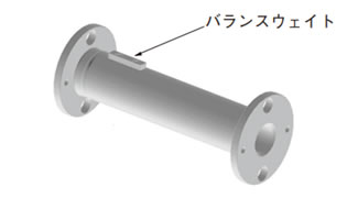
バランスウェイト取付イメージ図
軸間距離が長い場合の注意事項
軸間距離が長い場合は中間軸の軸受が不要でスペーサ部分がフローティング状態で使用できるロングスペーサタイプをご用意しております。是非ご利用ください。
ロングスペーサタイプ
なお、お客様の都合によりロングスペーサの代わりに中間軸を用意される場合は、縄跳び現象を避けるため中間軸は軸受等で固定してください。この場合のディスクカップリングはスペーサタイプを推奨します。
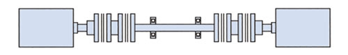
スペーサタイプ + 固定中間軸 + スペーサタイプ
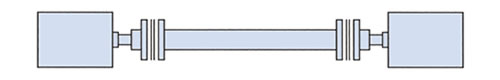
軸間距離が短く、中間軸をフローティング状態で使用される場合は必ずシングルタイプをご使用ください。
シングルタイプ + フローティング中間軸 +シングルタイプ
スペーサタイプを使用されますと著しい縄跳び現象が発生し非常に危険ですので絶対に避けてください。
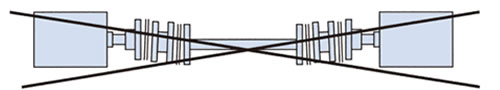
スペーサタイプ + フローティング中間軸 + スペーサタイプ
特にギヤカップリング、ローラチェーンカップリング等からディスクカップリングへの置換えの場合はご注意ねがいます。
