技術資料 減速機 ウォーム減速機 取扱
ここでは、EWJ・EWJM(R)・EW・EWM(R)、SWJ・SWJM(R)・SW・SWM(R)、TDシリーズ取扱に関する一般事項について記載しています。
詳細につきましては、製品に添付しています取扱説明書をご参照ください。
4. 据付
周囲温度が0℃~40℃で、なるべく風通しの良いほこりや湿気の少ない所に据付てください。
腐食性の液体やガスのある場所、引火性・爆発性のある場所での使用は避けてください。
また、屋外等でご使用の際には、雨等が直接かからないようカバー等をつけてご使用ください。
- (1)減速機の被動軸への取付け・取外しに際して、機械・装置の電源を必ず切って作業してください。
- (2)減速機の被動軸への取付け・取外しに際して、必ず減速機ケーシング上面の吊りボルトを用い、入出力軸にはワイヤなど絶対に掛けないでください。
- (3)減速機の被動軸への取付け・取外しに際して、減速機のバランスを取り、安定状態にあることをご確認ください。アンバランスな状態での作業は、減速機が回転し大変危険です。必ず安定状態を確保してください。
- (4)SWJ25~63、SWJM(R)35~63には吊りボルトはありませんので、減速機を両手で持ち、出力軸を被動軸と平行にした状態で、被動軸への挿入、被動軸からの抜き取りを行ってください。
4-1. 出力中実軸タイプ
出力軸中実タイプの据付は脚取付(EWJ・EWJM(R)・EW・EWM(R)・TD-S)とフランジ取付(SW・SWM80~200)の2通りがあります。
4-1-1. 脚取付の場合(EWJ・EWJM(R)・EW・EWM(R)・TD-S)
- ・標準の据付方向であるかどうかをご確認ください。
- ・据付方向が標準以外の場合、油量および一部潤滑方式が異なりますので、図面を参照するかまたはご照会ください。
- ・据付けの基準面は、無理がかからないよう平滑で十分強固なものとし、据付角度は、±1°以内としてください。
- ・据付ボルトは、JIS強度区分10.9T相当品をご使用ください。
据付推奨ボルト
EWJ・EWJM サイズ EWJ25 EWJ35 EWJ42 EWJ50 EWJ63 EWJ70 推奨ボルト M6×15 M8×15 M10×20 M8×25 M10×30 M12×35 EW・EWM サイズ EW80 EW100 EW125 EW150 EW175 EW200 推奨ボルト M12×40 M14×45 M16×55 M20×60 M20×70 M24×80 TD-S サイズ TD125 TD150 TD175 TD200 TD225 TD250 TD280 TD315 推奨ボルト M16×55 M20×60 M20×70 M24×80 M24×80 M30×100 M30×100 M30×110 - ・ハウジングに変形を生じるような据付けは絶対に避けてください。
- ・減速機は潤滑油を封入の上出荷しています。運搬時の油洩れ防止のため、給油口はプラグで栓をしていますので、ご使用前に「プラグ栓」を付属の「プレッシャーベント」に付け替えてください。プラグ栓のままで連続運転をした場合、内圧が上昇し、オイルシール部から油が漏れるおそれがあります。
注)EWJ25~70・EWJM42~70(高減速も含)およびSWJ25~70・SWJM35~70にはプレッシャーベントは必要ありませんので、入荷時の状態でご使用ください。
4-1-2. フランジ取付の場合(EWJ25~42・EWJM(R)42・SW80~200・SWM(R)80~200)
減速機の固定は減速機ケースフランジ面を利用します。次の点に注意してください。
1. SW・SWM(R)の出力中実軸タイプの場合
- (1)減速機の固定にはケースフランジ面タップを利用し、位置決めにはケースインローを利用してください。
- (2)被動軸のラジアル方向の心振れ、入出力の連結、角度を調整し、減速機を据付けてください。
- (3)フランジ面の推奨ボルトサイズは下表を参照してください。
(表中のボルトサイズ:深さはタップ深さです。)
注)ケースインローを用いず、入出力の連結を先に行った後、フランジ面の固定を行った場合は、シャフト、ベアリングに予期せぬ荷重が発生し減速機の寿命を短くする恐れがあります。
フランジ面の推奨ボルトサイズ
減速機サイズ SW80 SW100 SW125 SW150 SW175 SW200 ボルトサイズ M10 深さ 20 M10 深さ 20 M12 深さ 25 M12 深さ 25 M14 深さ 30 M16 深さ 30 取付 PCD 180 205 255 300 350 380 取付本数 6ヵ所等配 6ヵ所等配 6ヵ所等配 8ヵ所等配 8ヵ所等配 8ヵ所等配
2. EWJ25~42・EWJM(R)42の場合
減速機本体を床面や壁面に取付ける場合には次の点に注意してください。
- (1)減速機の固定にはフランジ面の取付け穴を利用してください。減速機の据付面よりもケース端面が出ていますので、減速機本体と据付面の間に必ず下表、図のように、クリアランス(ΦD、t)以上を確保してください。
- (2)被動軸のラジアル方向の心振れ、入出力の連結、角度を調整し、減速機を据付けてください。
- (3)減速機のフランジ面の推奨ボルトサイズおよびピッチは下表を参照ください。
注)入出力の連結を先に行った後、フランジ面の固定を行った場合は、シャフト、ベアリングに予期せぬ荷重が発生し減速機の寿命を短くする恐れがあります。
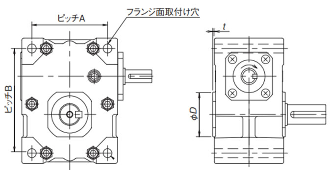
据付面に必要なクリアランス量
| サイズ | ΦD | t |
|---|---|---|
| EWJ25 | 46 | 3 |
| EWJ35 | 48 | 1.5 |
| EWJ42 | 63 | 3 |
取付ボルトサイズ、本数、ピッチ
| サイズ | 取付ボルトサイズ | ピッチ A |
ピッチ B |
|---|---|---|---|
| EWJ25 | M6×60 4本 | 57 | 76 |
| EWJ35 | M8×80 4本 | 71 | 96 |
| EWJ42 | M10×90 4本 | 88 | 111 |
推奨締付トルク
| サイズ | 締付トルク (N・m) |
締付トルク {kgf・m} |
|---|---|---|
| EWJ25 | 4.9 ~ 5.9 | 0.5 ~ 0.6 |
| EWJ35 | 12 ~ 14 | 1.2 ~ 1.4 |
| EWJ42 | 24 ~ 27 | 2.4 ~ 2.7 |
4-2. 出力中空軸タイプ
減速機の回転止めの方法として、「トルクアーム取付け」、「フランジ取付け」「脚取付(EW-H(出力中空軸タイプ)のみ)」の3通りの方式があります。被動軸の軸径公差はg7を推奨します。
- (1)被動軸への減速機の挿入に際して、被動軸の外周部および減速機の出力中空軸内部に傷やゴミの無いことを必ずご確認ください。
- (2)挿入を容易にするため、被動軸にグリースまたは二硫化モリブデン等を塗布してください。
- (3)挿入が固い場合には、出力中空軸の端面をソフトハンマーで軽くたたいて挿入してください。なお、この際オイルシールに傷を付けないように十分注意してください。
- (4)中空軸キー溝は、新JIS並級で仕上げています。キー長さについては下記「推奨被動軸長さ」を参考にしてください。
推奨被動軸長さ(下記 図1、図2を参照ください)
| シリーズ | SWJ | SW・EW | SW・EW・TD | TD | ||||||||||||
|---|---|---|---|---|---|---|---|---|---|---|---|---|---|---|---|---|
| 減速機サイズ | 25 | 35 | 42 | 50 | 63 | 70 | 80 | 100 | 125 | 150 | 175 | 200 | 225 | 250 | 280 | 315 |
| 出力軸長さ:A | 60 | 70 | 80 | 108 | 128 | 130 | 148 | 174 | 200 | 250 | 270 | 290 | 320 | 356 | 404 | 454 |
| 推奨被動軸長さ:L | 58 | 68 | 78 | 89 | 109 | 106 | 122 | 146 | 170 | 220 | 238 | 258 | 272 | 303 | 344 | 386 |
4-2-1. トルクアーム取付け・取外し
1. 取付け手順
注)入力両軸タイプの減速機をラインシャフトにて連結する据付は避けてください。
- (1)減速機にトルクアームをボルトにて取付けてください。注)トルクアームをご購入頂いている場合は、附属のボルトをご使用ください。お客様にてトルクアームを製作される場合は、強度区分10.9相当ボルトをご使用ください。
- (2)被動軸に減速機を挿入してください。
- (3)被動軸に減速機を軸方向に固定してください。
- ・SWJ25~42の場合、図1のように出力軸端にエンドプレートで固定することを推奨します。
- ・SWJ50~70・SW80~200・EW80-H~200-H(出力中空タイプ)・TD125H~315Hの場合、図2のように出力中空軸の止め輪溝を使い、ストップリングとエンドプレートで固定することを推奨します。(出力中空軸詳細寸法は製品ページを参照ください。)
- (4)減速機の据付け姿勢が決まった後、減速機が被動軸と共回りしないように、トルクアームを固定してください。その際、トルクアームは、軸方向に自由度を持たせてください。
- 注)減速機より先にトルクアームの先端を固定しますと、減速機の破損に繋がる可能性がありますので、くれぐれも作業手順をお守りください。(EW80-H~200-Hは脚取付です。出力中空軸と被動軸を固定後、被動軸を支持するベアリング位置を設定ください。)
- 注)エンドプレートの製作は、抜きプレートを兼用させた下記表1の寸法・形状を推奨します。
図1 SWJ25~42
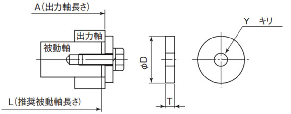
図2 SWJ50~70・SW80~200
EW80-H~200-H・TD125H~315H
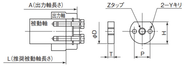
表1 エンドプレート(抜きプレート兼用)推奨寸法
| サイズ | 出力軸 穴径 |
プレート推奨寸法 | プレート用ボルト (バネ座金付) |
ストップリング サイズ |
|||||
|---|---|---|---|---|---|---|---|---|---|
| ΦD | T | H | Z | Y キリ | P | ||||
| SWJ25 | Φ12 | 16 | 4.5 | - | - | 5.5 | - | 1-M5×15 | - |
| SWJ35 | Φ20 | 26 | 6 | - | - | 9 | - | 1-M8×25 | - |
| SWJ42 | Φ25 | 32 | 6 | - | - | 9 | - | 1-M8×25 | - |
| SWJ50 | Φ30 | 29.6 | 9 | 25 | M12 | - | - | 1-M10×40 | C 30 |
| SWJ63 | Φ35 | 34.6 | 9 | 30 | M12 | - | - | 1-M10×40 | C 35 |
| SWJ70 | Φ40 | 39.6 | 12 | 34 | M12 | 2- 6.6 | 24 | 2-M6×40 | C 40 |
| EW/SW80 | Φ50 | 49.6 | 12 | 44 | M16 | 2- 9 | 30 | 2-M8×45 | C 50 |
| EW/SW100 | Φ55 | 54.6 | 14 | 48 | M16 | 2-11 | 32 | 2-M10×55 | C 55 |
| EW/SW125 | Φ70 | 69.5 | 14 | 62 | M24 | 2-14 | 44 | 2-M12×60 | C 70 |
| EW/SW150 | Φ80 | 79.5 | 17 | 70 | M24 | 2-14 | 52 | 2-M12×65 | C 80 |
| EW/SW175 | Φ90 | 89.5 | 17 | 80 | M30 | 2-14 | 60 | 2-M12×65 | C 90 |
| EW/SW200 | Φ100 | 99.5 | 17 | 89 | M30 | 2-18 | 65 | 2-M16×75 | C100 |
| TD125 | Φ70 | 69.5 | 14 | 62 | M24 | 2-14 | 44 | 2-M12×60 | C 70 |
| TD150 | Φ80 | 79.5 | 17 | 70 | M24 | 2-14 | 52 | 2-M12×65 | C 80 |
| TD175 | Φ90 | 89.5 | 17 | 80 | M30 | 2-14 | 60 | 2-M12×65 | C 90 |
| TD200 | Φ100 | 99.5 | 17 | 89 | M30 | 2-18 | 65 | 2-M16×75 | C100 |
| TD225 | Φ110 | 109.6 | 20 | 99 | M30 | 2-18 | 65 | 2-M16×85 | C110 |
| TD250 | Φ125 | 124.4 | 20 | 113 | M30 | 2-18 | 70 | 2-M16×85 | C125 |
| TD280 | Φ130 | 129.4 | 24 | 118 | M36 | 2-22 | 80 | 2-M20×100 | C130 |
| TD315 | Φ160 | 159.4 | 24 | 146 | M36 | 2-22 | 85 | 2-M20×100 | C160 |
2. 取外し手順
- (1)減速機を吊りボルトを用い吊り下げてください。
- (2)被動軸に減速機を固定(軸方向)しているエンドプレートのボルトを緩めてください。
- (3)軸の回転方向を止めている、トルクアームの先端をフリーにしてください。
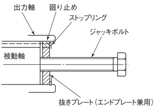
- (4)ケースと出力中空軸の間に余分な力が掛からないよう、被動軸から出力中空軸を抜いてください。抜きプレート(表1)とジャッキボルト(表2)をご準備頂き、図3の要領でジャッキボルトを取付ければスムーズな取外しが可能です。
表2 ジャッキボルト寸法
| サイズ | 出力軸穴径 | ジャッキボルト (総ネジ) |
サイズ | 出力軸穴径 | ジャッキボルト (総ネジ) |
|---|---|---|---|---|---|
| SWJ50 | Φ30 | M12×80 | TD125H | Φ70 | M24×150 |
| SWJ63 | Φ35 | M12×80 | TD150H | Φ80 | M24×150 |
| SWJ70 | Φ40 | M12×80 | TD175H | Φ90 | M30×180 |
| EW/SW 80 | Φ50 | M16×100 | TD200H | Φ100 | M30×180 |
| EW/SW100 | Φ55 | M16×100 | TD225H | Φ110 | M30×180 |
| EW/SW125 | Φ70 | M24×150 | TD250H | Φ125 | M30×180 |
| EW/SW150 | Φ80 | M24×150 | TD280H | Φ130 | M36×250 |
| EW/SW175 | Φ90 | M30×180 | TD315H | Φ160 | M36×250 |
| EW/SW200 | Φ100 | M30×180 |
図3 ジャッキボルト取付要領
4-2-2. フランジ取付け・取外し
1. 取付け手順
被動機に減速機を固定する場合(ラジアル荷重が減速機に作用しない場合)
- (1)被動軸に減速機を挿入してください。
- (2)固定に際しては、ケースのフランジ面タップを利用します。
- ・SWJ25~42の場合、フランジ面の穴を利用してボルトで固定してください。
- ・ボルトサイズ、取付け寸法、ピッチ等は上記4-1-2.の2項の表、図を参照してください。
- (3)位置決めには、ケースのインローの利用をお勧めします。
(SWJ25にインローはありません。)
注)フランジ取付けでは、エンドプレートは不要です。
エンドプレートで出力中空軸を固定しますと、出力中空軸のベアリングにスラスト力を与え、ベアリングを傷める可能性があります。
被動機に減速機フランジ取付けで固定する場合(ラジアル荷重が減速機に作用する場合)
- (1)被動軸に減速機を挿入してください。
- (2)被動軸のラジアル方向の心振れを調整し、アキシャル方向は自由な状態で、減速機を据え付けてください。
- (3)減速機の固定にはケースのフランジ面タップの利用、位置決めにはケースのインローの利用をお勧めします。 (SWJ25にインローはありません。)
- (4)減速機を固定した後、被動軸のアキシャル方向を固定してください。
注)被動軸側のアキシャル方向を先に固定しますと、中空軸のベアリングにスラスト力を与え、ベアリングを傷める可能性があります。
2. 取外し手順
被動機に減速機が固定されている場合(ラジアル荷重が減速機に作用しない場合)
- (1)被動機と減速機を固定しているフランジボルトを緩めてください。
- (2)ケースと出力中空軸の間に余分な力が掛からないよう、被動軸から出力中空軸を抜いてください。抜きプレート(表1)とジャッキボルト(表2)をご準備頂き、図3の要領でジャッキボルトを取付ければスムーズな取外しが可能です。
被動機に減速機フランジ取付けで固定する場合(ラジアル荷重が減速機に作用する場合)
- (1)被動軸をバランスのとれた安定状態に保持してください。
- (2)被動機と減速機を固定しているフランジボルトを緩めてください。
- (3)ケースと出力中空軸の間に余分な力が掛からないよう、被動軸から出力中空軸を抜いてください。抜きプレート(表1)とジャッキボルト(表2)をご準備頂き、図3の要領でジャッキボルトを取付ければスムーズな取外しが可能です。
4-2-3. 脚取付の取付け・取外し(EW-H 出力中空軸タイプ)
取付け、取外しは4-1-1項の脚取付および4-2-1項のトルクアーム取付け、4-2-2項のフランジ取付けを参考に被動機と減速機の心出しを確実に行ってください。
心出しを誤ると、予期せぬ荷重が発生し、ベアリング、シャフト等が破損する恐れがあります。
