技術資料 減速機 ウォーム減速機 取扱
ここでは、EWJ・EWJM(R)・EW・EWM(R)、SWJ・SWJM(R)・SW・SWM(R)、TDシリーズ取扱に関する一般事項について記載しています。
詳細につきましては、製品に添付しています取扱説明書をご参照ください。
5. 連結
5-1. 回転方向の確認
ウォームはすべて右ねじれです。入力軸と出力軸の回転関係をご確認ください。
5-2. 連結
- ・減速機の入・出力軸に、プーリ、スプロケット、カップリングを取付ける際には、軸に衝撃力や過大なスラスト荷重を掛けないでください。
- ・心出しは正確に行ってください。心出し精度については、ご使用されるプーリ・スプロケット・カップリングなど、それぞれのカタログまたは取扱説明書をご参照ください。
- ・軸の偏心や許容値以上のラジアル荷重やアキシャル荷重は、振動や騒音の原因となり、またギヤ・ベアリング・軸の寿命を短くします。
5-3. モータ取付(EWJM・EWM・SWJM・SWMシリーズのモータ取扱記号:Yに適用)
- ・モータ組込みに際し、減速機との締結は入力軸はホロータイプになっていますのでカップリングは使用しません。
- ・減速機の入力軸はご指定のモータ容量に合わせて軸穴加工・キー溝加工をしています。なおモータ組込みのキーは、モータに付属されているキーをご使用ください。
- ・モータ取付要領は下記手順にて安全に留意し作業ください。
モータ取付要領
| 手順 | 取付け要領 | 注意事項 |
|---|---|---|
| 1 |
減速機をモータが取付けやすいように設置してください。 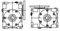
|
運搬の際は、安全に対し、十分に配慮してください。 |
| 2 |
モータの出力軸キーと減速機入力軸キー溝の位相を合わせてください。 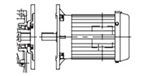
|
モータを運搬する際は、安全に対し、十分に配慮してください。 軸の偏心がないよう心出しを完全にしてください。 |
| 3 |
モータの出力軸を減速機の入力軸に静かに挿入してください。 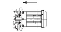
|
モータの出力軸および減速機入力軸穴にも、グリースを塗布してください。 グリース銘柄:Mobil SHC Grease 681WT(エクソンモービル製) |
| 4 |
付属の六角穴付ボルトをバネ座金でモータフランジに完全に固定してください。 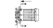
|
モータが減速機に正しく挿入している事を確認してから、ボルトを締め付けてください。 ボルトサイズ、強度区分に相当する締付トルクにて締め付けてください。 |
- 注)減速機が同一サイズでも、モータ容量によって、モータのフランジ径は異なります。また、減速機入力軸の軸穴加工・キー溝加工も異なります。
- 注)減速機とモータの連結は、モータの吊りフックを使用し安全かつ慎重に作業してください。
減速機とモータの連結がジョーフレックスカップリングの場合
(EWJM(R)42、EWJM(R)50~70 高減速タイプ、SWJM(R)35~70のモータ取扱記号:Yに適用)
- ・減速機側のカップリング・ハブは、出荷時セット(キーおよび止めビス)されています。移送時等での『ゆるみ』発生がないかを念の為ご確認ください。
- ・モータ側のカップリング・ハブは、ご指定のモータ容量に合せ軸穴加工、キー溝加工をし、付属出荷しています。
*モータ軸長さ調整用カラーを付属していますので、忘れずに組込みください。
注)モータ側のカップリング・ハブ組込みに際しては、減速機に付属されているキーおよび止めビスをご使用ください。
- ・インサートは、付属出荷している物をご使用ください。
- ・モータ・フランジ取付ボルトおよびバネ座金は、付属出荷しております。下表にてご確認ください。
| モータ容量 | 0.1kW | 0.2kW | 0.4kW | 0.75kW | 1.5kW | 2.2kW | 3.7kW | 5.5kW |
|---|---|---|---|---|---|---|---|---|
| ボルトサイズ | M8×25mm | M8×25mm | M8×25mm | M10×30mm | M10×30mm | M12×30mm | M12×30mm | M12×35mm |
| バネ座金 | M8用 | M8用 | M8用 | M10用 | M10用 | M12用 | M12用 | M12用 |
| 数量 | 4 | 4 | 4 | 4 | 4 | 4 | 4 | 4 |
モータ取付要領:下記手順にて安全に留意し作業ください
| 手順 | 取付け要領 | 注意事項 |
|---|---|---|
| 1 |
減速機をモータが取付けやすいように設置してください。 
|
運搬の際は、安全に対し、十分に配慮してください。 |
| 2 |
モータの出力軸に、グリースを薄く塗布して、入カラーを挿入後、ジョーフレックスカップリングを取り付けてください。 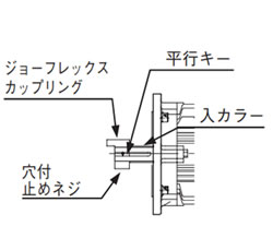
|
カップリングを挿入する際、ハンマーなどで強くカップリングをたたかないでください。 モータを運搬する際は、安全に対し、十分に配慮してください。 |
| 3 |
減速機のカップリング側にジョーフレックスカップリングのインサートを入れます。 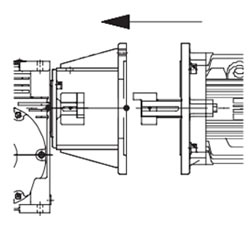
|
モータ側のカップリングを連結する時、インサート部にスムーズに挿入してください。 引っ掛り等、スムーズに挿入できない場合は、無理に押し込まず、再度位相合せ、心出しを行ってください。 |
| 4 |
付属の六角穴付ボルトをバネ座金でモータフランジに完全に固定してください。 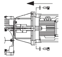
|
モータが減速機に正しく挿入している事を確認してから、ボルトを締め付けてください。 ボルトサイズ、強度区分に相当する締付トルクにて締め付けてください。 |
注)減速機とモータの連結は、モータの吊りフックを使用し安全かつ慎重に作業してください。
