技術資料 減速機 ウォーム減速機 モータ仕様
ブレーキ
1. ブレーキ特性
| モータ出力 | 三相 | 0.1kW | 0.2kW | 0.4kW | 0.75kW | 1.5kW | 2.2kW | 3.7kW | 5.5kW |
|---|---|---|---|---|---|---|---|---|---|
| ブレーキ形番 | 三相 200V | SLB01 | SLB02 | SLB04 | SLB07E | SLB15 | SLB22 | VNB371K NB-31190 | VNB55KE |
| 三相 400V | SLB01 | SLB02 | SLB04V | SLB07E 180V | SLB15 180V | SLB22 180V | VNB371KV NB-31192 | VNB55KE | |
| DCモジュール 形番 |
三相 200V | DM200D | DM200D | PM180B | |||||
| 三相 400V | DM400D | ||||||||
| 定格トルク | 静摩擦トルク N・m | 0.98 | 1.96 | 3.92 | 7.35 | 15 | 22 | 37 | 55 |
| {kgf・m} | 0.1 | 0.2 | 0.40 | 0.75 | 1.50 | 2.20 | 3.77 | 5.61 | |
| 動摩擦トルク N・m | 0.78 | 1.57 | 3.14 | 5.88 | 12.0 | 17.6 | 29.6 | 44 | |
| {kgf・m} | 0.08 | 0.16 | 0.32 | 0.60 | 1.20 | 1.79 | 3.02 | 4.48 | |
| 電圧 | 三相 200V | DC90V | DC90V | 瞬時 180V 常時 50V |
|||||
| 三相 400V | DC180V | ||||||||
| 電流 at20 ℃ A |
三相 200V | 0.178 | 0.178 | 0.232 | 0.273 | 0.289 | 0.289 | 0.261 | 0.253 |
| 三相 400V | 0.142 | 0.145 | 0.145 | 0.135 | |||||
| 容量 | at 20 ℃ W | 16.0 | 16.0 | 20.9 | 24.6/25.5 | 26.0/26.1 | 26.0/26.1 | 26.1/26.1 | 12.6/40.7 |
| 初期ギャップ mm | 0.15 ~ 0.20 | 0.15 ~ 0.20 | 0.15 ~ 0.20 | 0.15 ~ 0.20 | 0.15 ~ 0.20 | 0.15 ~ 0.20 | 0.3 | 0.35 | |
| 限界ギャップ mm | 0.5 | 0.5 | 0.5 | 0.5 | 0.5 | 0.5 | 1.2 | 1.2 | |
| 慣性モーメント kg・m2 | 0.02×10⁻³ | 0.04×10⁻³ | 0.04×10⁻³ | 0.11×10⁻³ | 0.21×10⁻³ | 0.50×10⁻³ | 0.50×10⁻³ | 1.70×10⁻³ | |
| GD2 kgf ・m2 | 0.10×10⁻³ | 0.15×10⁻³ | 0.15×10⁻³ | 0.44×10⁻³ | 0.80×10⁻³ | 2.00×10⁻³ | 2.00×10⁻³ | 6.8×10⁻³ | |
| 総制動仕事量 J {kgf・m} |
1.31×10⁸ | 1.85×10⁸ | 1.85×10⁸ | 3.66×10⁸ | 3.73×10⁸ | 3.73×10⁸ | 13.5×10⁸ | 24.7×10⁸ | |
| 1.34×10⁷ | 1.89×10⁷ | 1.89×10⁷ | 3.73×10⁷ | 3.81×10⁷ | 3.81×10⁷ | 13.8×10⁷ | 25.2×10⁷ | ||
| 許容起動頻度 | 10 回/分 | ||||||||
| 制動遅れ時間 S(参考値) |
交流同時切り | 0.18 ~ 0.25 | 0.15 ~ 0.21 | 0.14 ~ 0.17 | 0.20 ~ 0.24 | 0.30 ~ 0.45 | 0.30 ~ 0.45 | 0.50 ~ 0.70 (0.40 ~ 0.60) |
- |
| 交流別切り | 0.11 ~ 0.18 | 0.09 ~ 0.12 | 0.06 ~ 0.09 | 0.10 ~ 0.13 | 0.10 ~ 0.13 | 0.10 ~ 0.13 | 0.20 ~ 0.40 | - | |
| 交流別操作 | 0.11 ~ 0.18 | 0.09 ~ 0.12 | 0.06 ~ 0.09 | 0.10 ~ 0.13 | 0.10 ~ 0.13 | 0.10 ~ 0.13 | 0.20 ~ 0.40 | 0.03 ~ 0.05 | |
| 直流別切り | 0.05 ~ 0.07 | 0.04 ~ 0.06 | 0.03 ~ 0.05 | 0.04 ~ 0.06 | 0.01 ~ 0.06 | 0.01 ~ 0.06 | - (0.02 ~ 0.04) |
- | |
- 注1)定格トルクは、すり合わせ後の静摩擦トルク・動摩擦トルクを表します。
- 注2)制動遅れ時間は参考値であり、ブレーキの状態・使用条件・個体差などにより異なる場合があります。制動遅れ時間を短くしたい場合(昇降装置など)は直流別切りをお奨めします。
- 注3)電流、容量は200V時/400V時の値です。
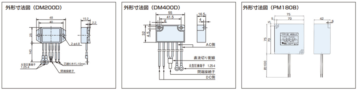
2. 整流器(DCモジュール)
DCモジュールは内蔵し、モータリード線と結線済みです。直流別切り回路を採用される場合には、注文時にご指示いただくか、こちらの結線図に基づいて接続ください。
制御盤内にご使用されるなど、DCモジュールを別納入にてご必要な場合は、注文時にご指示ください。
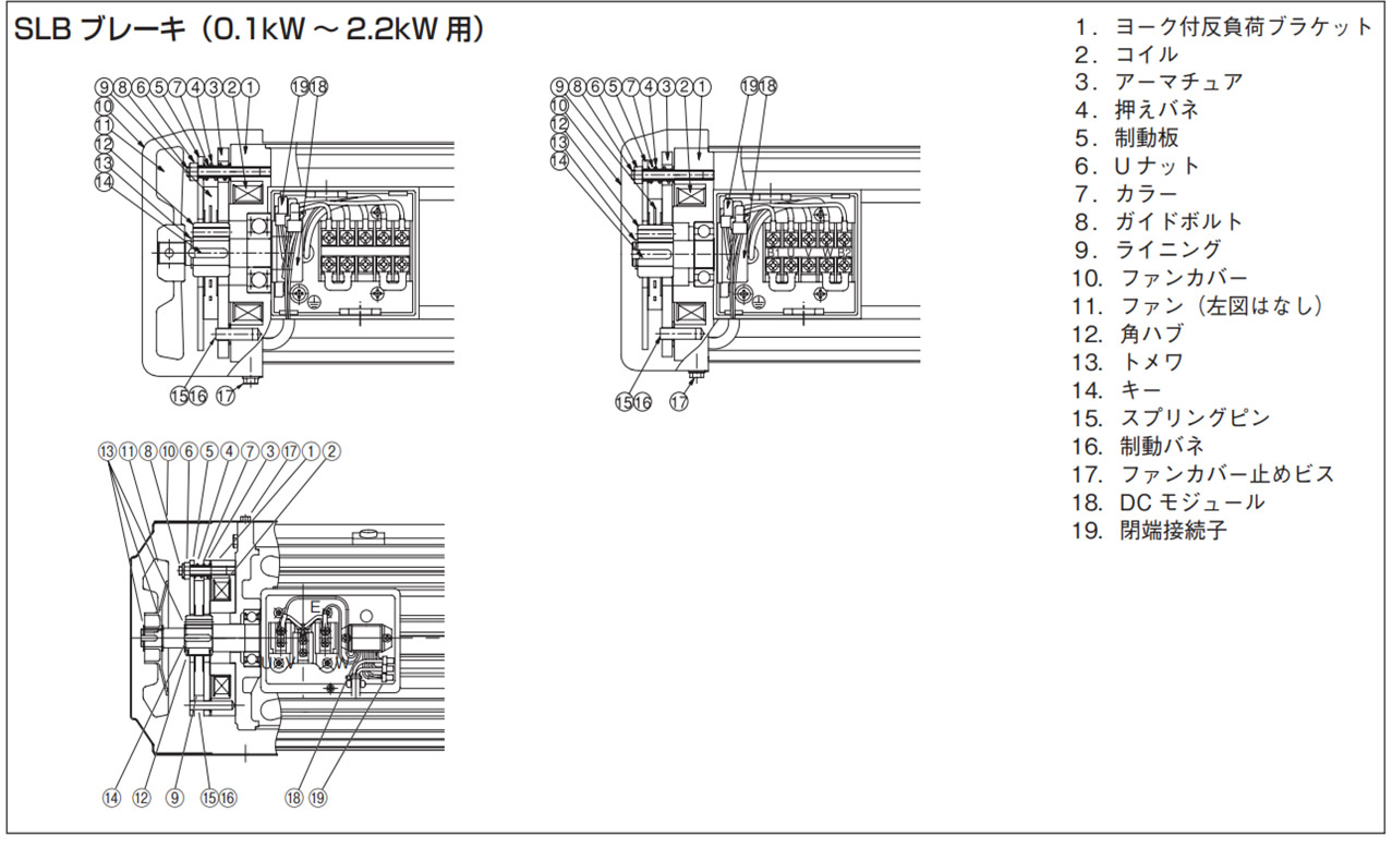
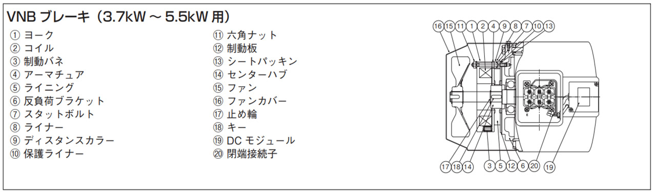
3. ブレーキ部構造
※手動解放[標準装備:0.1kW~2.2kW]
- ・出力軸に負荷が作用していない状態にして解放操作をしてください。
- ・ファンカバーを外してネジを取付けてください。
- ・作業終了後、必ずネジを外しファンカバーを取付けてから運転を開始してください。
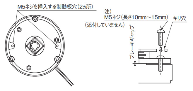
注)1.5kW、2.2kW は、M6ネジとなります。
