技術資料 減速機 サーボモータ用減速機TERVO 取扱
ここでは、TERVO HMTK、GMTK、SWJMK、SWMK、EWJMK、EWMKシリーズ取扱に関する一般事項について記載しています。
詳細につきましては、製品に添付しています取扱説明書をご参照ください。
据付
1. 据付方向
- ・HMTK、GMTK、SWJMK、EWJMK
据付方向に制限はありません。水平・垂直・傾斜いずれの方向にも取付けられます。 - ・SWMK、EWMK
減速機サイズ80、100は水平取付が標準据付です。その他の据付方向の際は、手配時にご指示ください。
取付
1. 脚取付形
- (1)据付台は運転による振動の影響が少ない強固で平面度のよいものを用い、据付面のゴミ、異物を除去した後にボルト4本にてしっかりと固定してください。
- (2)カップリングにて連結する場合、心出しを確実に行ってください。軸の偏心はベアリング、ギヤ、軸の寿命を短くし、騒音や振動の原因となります。
- (3)チェーンやベルトの心出しは正確に行い、出力軸に規定値以上の荷重がかからないよう張りを調節してください。
- (4)連結の際、出力軸やカップリング、プーリ、スプロケットを強く叩くと出力軸の軸受を損傷する原因になりますので、ご注意ください。
2. フランジ取付形
- (1)フランジ取付形は運転による振動の影響が少ない強固で平面度のよいものを用い、据付面のゴミ、異物を除去した後にボルト4本にてしっかりと固定してください。
- (2)カップリングにて連結する場合、心出しを確実に行ってください。軸の偏心はベアリング、ギヤ、軸の寿命を短くし、騒音や振動の原因となります。
- (3)チェーンやベルトの心出しは正確に行い、出力軸に規定値以上の荷重がかからないよう張りを調節してください。
- (4)連結の際、出力軸やカップリング、プーリ、スプロケットを強く叩くと出力軸の軸受を損傷する原因になりますので、ご注意ください。
3. フェイスマウント形
- (1)機械本体に据付ける際、ケースのタップをご使用ください。
- (2)カップリングにて連結する場合、心出しを確実に行ってください。軸の偏心はベアリング、ギヤ、軸の寿命を短くし、騒音や振動の原因となります。
- (3)チェーンやベルトの心出しは正確に行い、出力軸に規定値以上の荷重がかからないよう張りを調節してください。
- (4)連結の際、出力軸やカップリング、プーリ、スプロケットを強く叩くと出力軸の軸受を損傷する原因になりますので、ご注意ください。
4. 中空軸形
4-1. 被動軸への取付
- (1)中空軸内径公差は、JIS H8で製作しております。被動軸の仕上げは、通常の場合h7、衝撃やラジアル荷重の大きい場合には、js6あるいはk6程度に少しはめあいを固くしご使用ください。
- (2)被動軸への取付の際に、被動軸表面および中空出力軸内径に二硫化モリブデングリースを塗布して挿入してください。
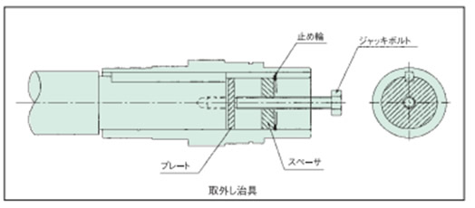
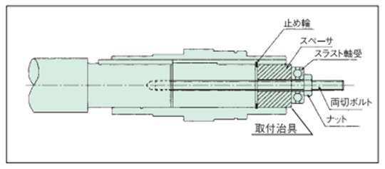
- (3)右記のような治具を製作してご使用頂ければ、スムーズに挿入いただけます。
4-2. 被動軸への固定
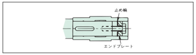
A. 被動軸に段差がある場合
下図のようにエンドプレートを製作して中空出力軸と被動軸を固定してください。
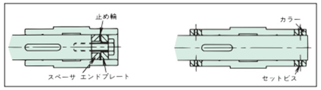
B. 被動軸に段差が無い場合の例
次のような2通りの固定方法があります。
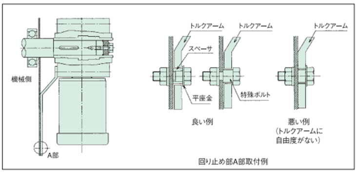
4-3. トルクアームの回り止め
- (1)トルクアームは、減速機の被動機械側に取付けてください。取付には六角穴付ボルトをご使用ください。
- (2)トルクアームの回り止め部には、減速機と被動軸の間に自由度を持たせ、回り止めボルトで決してトルクアームを固定しないでください。自由度がないと減速機内のベアリング損傷の原因となります。
- (3)起動頻度が多い場合および、正逆の繰返し運転の場合等はトルクアームと回り止めボルト(又はスペーサ)の間にゴムブッシュを取付けると衝撃が緩和されます。
4-4. 被動軸からの取外
- (1)ケーシングと中空出力軸の間に余分な力が掛からないように中空出力軸から被動軸を抜いてください。
- (2)右記のような治具を製作してご使用いただければ、スムーズに取外していただけます。