技術資料 減速機 マイタ・ベベルギヤボックス 選定
選定手順や注意事項等をご覧になりたい方は下記へお進みください。
製品シリーズの絞り込みや仮選定をご希望の方は
こちらをクリックしてください。
使用条件が決まっており詳細な選定をご希望の方は
こちらをクリックしてください。
ARAギヤボックス選定
選定に必要な条件
(1)負荷トルクまたは伝動kW (2)入力回転速度 (3)速比 (4)負荷の性質 (5)起動停止の頻度
選定手順
必要条件を考慮し、下記要領により選定を行います。
1. 使用係数の決定
カタログ記載の伝動能力表はすべて使用係数を1.0とした場合の値です。
使用条件により表1の使用係数表にて使用係数を決定してください。
表1 使用係数
| 負荷の性質 | 運転時間 | ||
|---|---|---|---|
| 2時間 | 10時間 | 24時間 | |
| 均一な荷重 | 1.00 (1.00) |
1.00 (1.25) |
1.25 (1.50) |
| 多少衝撃の伴う荷重 | 1.00 (1.25) |
1.25 (1.50) |
1.50 (1.75) |
| 大きな衝撃の伴う荷重 | 1.25 (1.50) |
1.50 (1.75) |
1.75 (2.00) |
注)
- 1. 起動停止が1時間に10回以上の場合あるいは原動機が多筒エンジンの場合は( )内の数値を使用してください。
- 2. 上記使用係数は一般的な目安です。使用条件を考慮して決定ください。
2.補正トルクまたは補正kWの決定
使用係数(表1)を考慮の上、補正トルクまたは補正kWを求めます。
補正トルクまたは補正kW = (ARAシリーズに掛かる負荷トルクまたは伝動kW) × 使用係数(表1)
3. 形式の決定
- ・使用回転速度において、補正トルクまたは補正kWを満足するサイズを伝動能力表(製品ページ参照)より選定してください。
また、起動停止時のピークトルクが選定したサイズの伝動能力の200%以内におさまっているか、確認してください。 - ・軸配置および回転関係は、上記の軸配置・回転関係より適当な形番を決定してください。
4. ラジアル荷重の確認
ラテラル軸、クロス軸にスプロケット、ギヤ、プーリなどを取付けて駆動する場合は、ラジアル荷重を下式にて確認してください。
・ラジアル荷重の確認式
許容ラジアル荷重 ≧
T × f × Lf
r
(許容ラジアル荷重)
- T = 補正トルク N・m
- f = O.H.L.係数(表2)
- Lf = 作用位置の係数(表3)
- r = スプロケット、プーリなどのピッチ円半径 m
注)ラジアル荷重を確認の結果、左式を満足しない場合には、r すなわちスプロケット、プーリなどのピッチ円半径をより、大きなものにする必要があります。
表2 O.H.L.係数(f)
| チェーン | 1.00 |
|---|---|
| ギヤ 歯付ベルト |
1.25 |
| Vベルト・強力歯付ベルト | 1.50 |
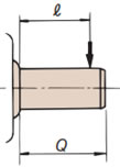
表3 作用位置の係数(Lf)
| 荷重が軸中央もしくは それより内側にかかる場合ℓ ≦ Q 2 |
Lf = 1 |
|---|---|
| 荷重が軸中央より 外側にかかる場合ℓ > Q 2 |
Lf = 2ℓ Q |
Q = 出力軸端の長さ ℓ = ラジアル荷重の作用位置
注)ラジアル荷重とアキシャル荷重が同時にかかる場合は当社までお問合せください。
