技術資料 小形コンベヤチェーン 取扱
チェーンの切り方
購入されたチェーンの長さを変更する場合は、下記手順でチェーンの切継ぎを行ってください。
1. ピンのリベット部をグラインダで削る
外リンクの2本のピンの端(アタッチメントの付いている側)を、外プレートと同一面になるまでグラインダで削り落とします。
グラインダ作業ではチェーンを過熱しないよう気をつけてください(図6、7)。
特にラムダチェーンの場合は、含油ブシュが加熱しないように、ゆっくりと作業を行ってください。
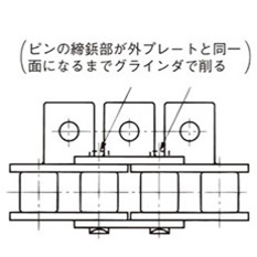
図6. アタッチメント付チェーン

図7. ピンの端部を削る
2. チェーンバイスや受け台にチェーンをセット
(1)Sローラ形(A、SA、EP、GNK1アタッチメント付)
アタッチメント側を上側にして、チェーンバイスの溝に分解する箇所のローラを通し、チェーンバイスの口金で軽く締付けます(図8、9)。
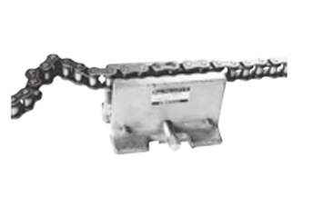
図8. チェーンバイスにチェーンをセット
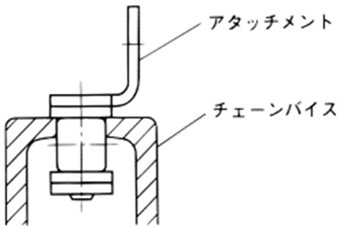
図9. チェーンをセットした断面
(2)Sローラ形(K、SKアタッチメント付)、Rローラ形(K、SKアタッチメント付)、プラRローラ形、プラコンビ(アタッチメント付)
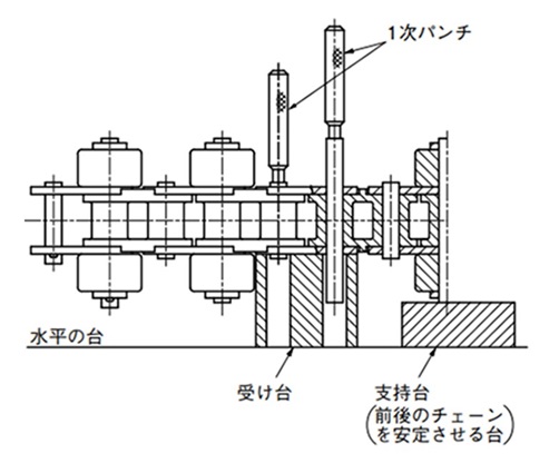
このタイプのチェーンは、図11-1のような受け台でチェーンを受けます。
また、別の方法としてスチール製のSローラ形に限ってチェーンバイスの端の方に抜こうとするピン部分を乗せます(図11-2)。
いずれの場合もチェーンを安定させるために、前後に適当な支え台を用意してください(図10)。
なお、この方式では、どのアタッチメント付も切離しができますが、3項のピンを抜く力が大きくなります。
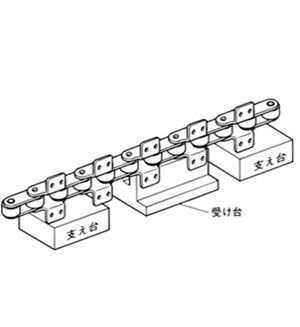
図10. 受け台と支え台
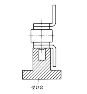
図11-1. 受け台の断面
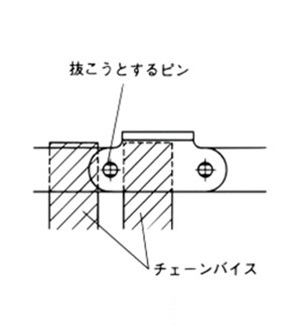
図11-2. チェーンバイスを使用
(3)Rローラ(A、SA、EP、アタッチメント付)...プラローラは適用できません。
チェーンバイスでアタッチメントの付いていない側のプレート部を挟み、Rローラを支えるようにします(図13)。
このときも、前後に適当な支え台を用意してください(図12)。
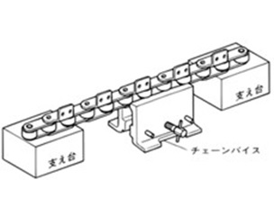
図12. チェーンバイスと支え台
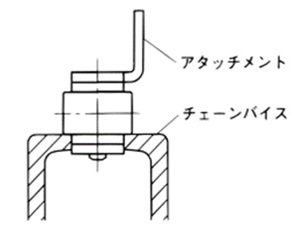
図13. チェーンをセットした断面
3. ピンを抜く
- (1)チェーンのサイズに合った一次パンチ(「ドライブチェーン&スプロケット」カタログアクセサリの項参照)をグラインダで削ったピンの頭に当て、一次パンチの頭をハンマでたたきます。この際、外リンクの一対のピンが平行に抜けるように交互にたたきます。外プレートからピンが抜ける直前までたたきます(図14)
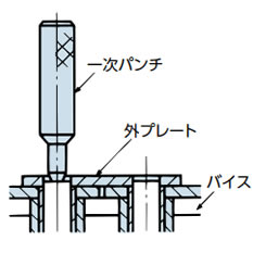
図14. 一次パンチでピンをたたく
- (2)二次パンチ(「ドライブチェーン&スプロケット」カタログアクセサリの項参照)とハンマを用いて、リンクから一対のピンを抜きます。ピンを抜いた部分のブシュが内プレートから抜けていないか、変形がないかチェックしてください。もし、抜けたり変形したときは、その部分は使わないでください。
4. プラコンビ(アタッチメントなしのチェーン)の切り方
- (1)チェーンの外プレートを受け台で受け、ピンの頭を専用パンチ(写真参照)で押えて、ハンマでパンチの頭を軽くたたきます(図15)。
- (2)このときエンプラ部分に大きな力をかけると、破損するおそれがありますので、ご注意ください。
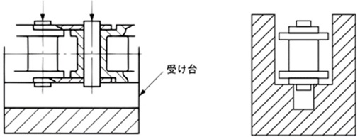
図15. プラコンビを受け台にセットした断面
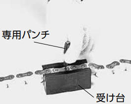
図16. プラコンビの分解
⚠ 安全上の注意
- 1. リベット形ピンの一端は、リベット部分を必ずグラインダで削り落してください。そのまま抜くと、かえって手間がかかったり、チェーンをいためます。
- 2. 取外した部品は再使用しないでください。
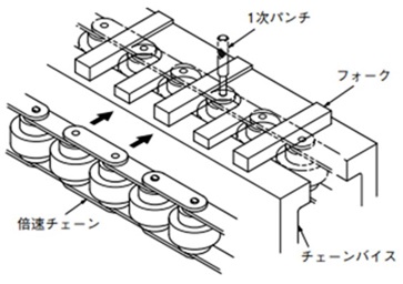
5. 倍速チェーンの切り方
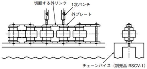
- (1)切断する外リンクのピン端部のリベットをハンドグラインダで削落とします。
- (2)チェーンバイス(または相当品)に倍速チェーン(スナップカバー付は切断部3リンク位はスナップカバーを外す)を乗せて一次パンチなどで上側の外プレートが外れるまでピンをたたき込みます。
- (3)フォーク状の工具とチェーンバイスによって切ることもできます。
6. サイドローラ付チェーンの切り方
本体ローラがS形の切り方
サイドローラ付プラコンビチェーンは下記に記しています。
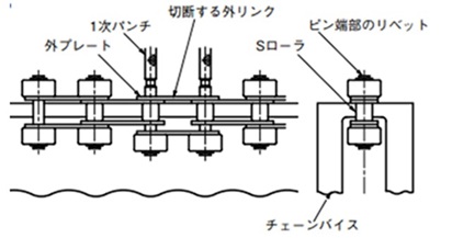
- (1)切断する外リンクを決めて認識マークを入れてください。
- (2)チェーンバイス(別売品)にチェーンを上図のようにセットし、ピン端部のリベット(片側の2ヵ所)をハンドグラインダなどで削り落とします。
- (3)チェーンのピン径よりも少し細いピン(当社別売品の一次パンチ相当品)を使って、2本のピンを抜きます。ピンが少し抜けた時に、上側の2個のサイドローラが取除けるようになります。 (上図は、サイドローラを取除いた状態)
- (4)ピンの端面が外プレートの上面に達するまでは、比較的小さいハンマでピンを直接たたいて抜きます。この時も2本のピンが同量ずつ抜けるようにピンを交互にたたいてください。
なお、左右のサイドローラにきずをつけない事が重要です。 - (5)一次パンチを使って、上側の外プレートが外れるまで、2本のピンを抜きます。
本体ローラがR形の切り方
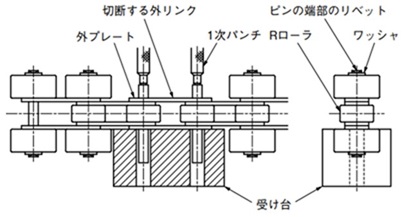
- (1)切断する外リンクを決めて認識マークを入れてください。
- (2)まず、4個のサイドローラを取除くために、ピン端部(4ヵ所)のリベット部をハンドグラインダで削り落とします。このとき、ワッシャを取除くためにワッシャ面までグラインダで削ります。
- (3)4個のサイドローラを取除きます。 (方法:「受け台」でサイドローラを受けてワッシャが外れるまで、ピン端面にパンチを当ててたたき抜きます。反対側も同様に行います。)
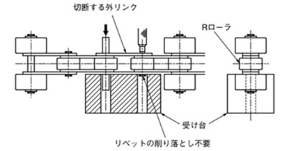
- (4)上図のように「受け台」にチェーンをセットし、一次パンチをハンマでたたき2本のピンを抜きます。「受け台」は適宜ご用意ください。
- (5)「本体ローラがS形の切り方」の(4)、(5)と同じ要領で作業を進めてください。
- (6)サイドローラが2リンク毎以上の間隔で付いている場合は、リベットを削る箇所が変わります。(下図)
サイドローラ付プラコンビの切り方
・サイドローラの取付けが千鳥形の場合
- (1)切断する外リンクを決めて認識マークを付けてください。
- (2)「本体ローラがS形の切り方」のように、チェーンバイスにチェーンをセットできますが、内リンクがエンプラのため破損します。したがって、この切り方は適用できません。
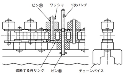
- (3)上図のように、ピン端部のワッシャをチェーンバイスで軽く締付けます。このチェーンのピン端部にはリベットを行ってありませんので、このまま分解に取りかかります。
- (4)チェーンのピン径よりも少し細いピン(当社別売品の一次パンチまたは相当品)で、大きい衝撃を与えないように、ゆっくりと一次パンチをハンマでたたいて、チェーンのピンを抜いていきます。(上図参照)上図のように、上側の外プレートからピンが抜けた位置で止めます。
- (5)ピン(a)とピン(b)を同じ要領で抜くと切断できます。上図は、既にピン(a)を所定の所まで抜いた後で、ピン(b)を抜き終った状態です。
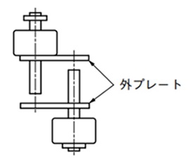
- (6)切断した外リンク(下図)は、破棄してください。
・サイドローラの取付けが平行形の場合
- (1)切断する外リンクを決めて認識マークを付けてください。
- (2)「本体ローラがS形の切り方」のように、チェーンバイスにチェーンをセットできますが、内リンクがエンプラのため破損します。したがって、この切り方は適用できません。
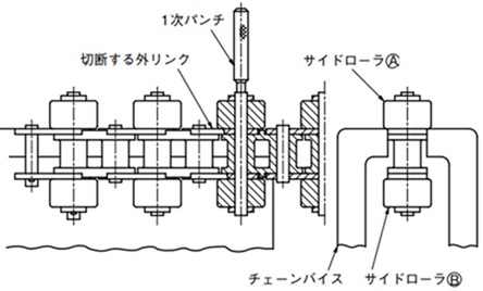
- (3)上図のように、上側のサイドローラ(A)をチェーンバイスで支え、軽くチェーンバイスを締付けます。このとき、図のように切断する外プレートをチェーンバイスの端の方に持ってきてください。
- (4)サイドローラ(A)のピン端部に一次パンチを当て、パンチを軽量のハンマでゆっくりとたたきます。サイドローラ(A)が下図のように外れます。
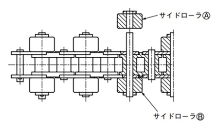
- (5)サイドローラ(B)は、チェーンの上下を逆にして(A)ローラと同じ要領で抜きます。
- (6)下図のように、(A)(B)のサイドローラを取除いたチェーンを「受け台」にセットし、一次パンチをハンマで軽くたたき、2本のピンを抜きます。上側の外リンクが外れるまでピンを抜いてください。(受け台は、適宜ご用意ください。)
7. トップローラ付チェーンの切り方
- (1)切断する外リンクに認識マークを入れてください。
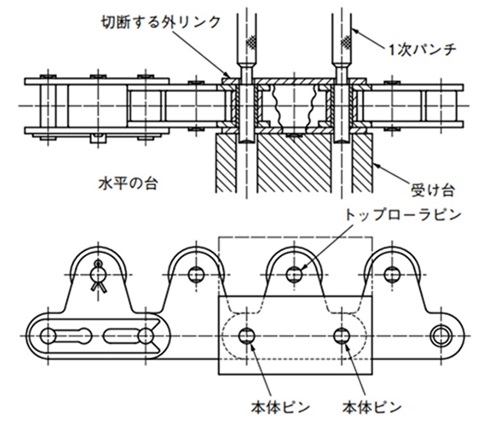
- (2)本体ピンおよびトップローラピンの端部のリベットをハンドグラインダなどで削り落とします。 (チェーンの片側だけ3ヵ所)
- (3)グラインダをかけた側を上側にして、図のように「受け台」にチェーンをセットします。「受け台」は適宜ご用意ください。
なお、トップローラピンを含めた3本のピンを同時に抜く時は、仮想線で示した部分を一体とした「受け台」を作ってください。 - (4)2本(3本)のピンが外プレートから外れる(図の位置)まで、一次パンチ(または相当品)をハンマでたたいてピンを抜きます。
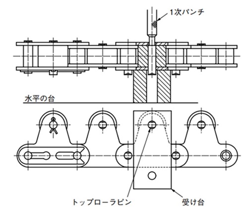
- (5)次にトップローラピンを抜くために、「受け台」を下図のようにセット替えします。(外リンクにトップローラが付いていない場合には、この作業はありません。)
- (6)トップローラピンを(4)項と同じように抜きます。
チェーンの継ぎ方
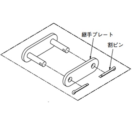
1. 継手リンクで連結
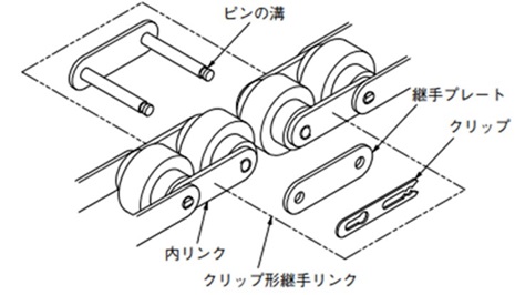
- 1)継手リンクを内リンクのつなぎ部に挿入し、継手プレートを取付けた後でクリップまたは割ピンで止めます。
- 2)継手プレートとピンの間は、すきまばめですので手作業で入れられます。
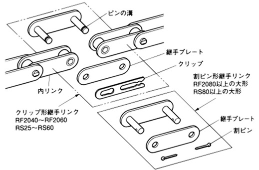
図17.アタッチメント付チェーンの連結
2. クリップの取付け
継手リンクのクリップの取付けは確実に行ってください。クリップの取付け忘れ、または取付け不備は思わぬ事故の原因となります。
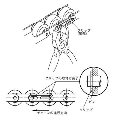
- 1)クリップは、RF2060・RS60以下のチェーンの継手リンクに使用しています。連結のときには、ピンに継手プレートを挿入後、クリップを継手リンクのピンの溝に確実に挿入してください(図18・19)。
- 2)クリップの脚部を拡げ過ぎると、正しく挿入できず脱落して思わぬ事故となりますので、注意を払ってください(図19・20)。
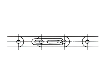
図18. クリップをピンの溝に挿入する
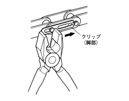
図19. クリップをペンチで止める
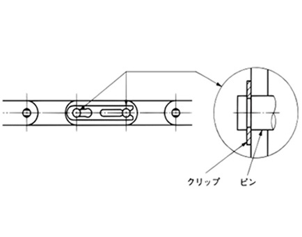
図20. クリップの取付け完了
- 3)クリップの取付け方向は、一般にチェーンの進行方向に対して下図のようになります(図21)。
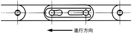
図21.クリップの取付方向
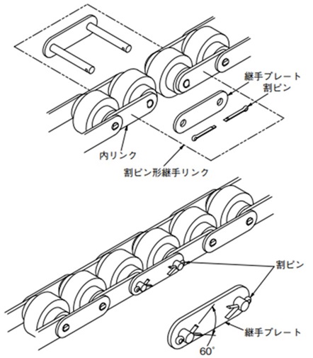
3. 割ピンの取付け
継手リンクの割ピンの取付けは確実に行ってください。割ピンの取付け忘れ、または取付け不備は思わぬ事故の原因となります。
- 1)割ピンの開脚は60°程度としてください(図22)。割ピンの再使用や市販の割ピンは使用しないでください。
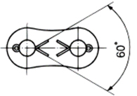
図22.割ピンの開脚
- 2)割ピンの開脚要領
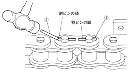
図23.
- (1)割ピンを割ピン穴に入れます。
- (2)割ピン径よりも少し太いピンで割ピンの頭を軽くたたくと割ピンの脚がわずかに開きます。
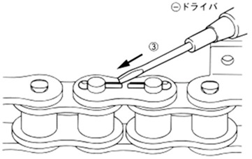
図24.
- (3)割ピンの脚がわずかに開いている箇所にマイナスドライバの先を差し込みます。
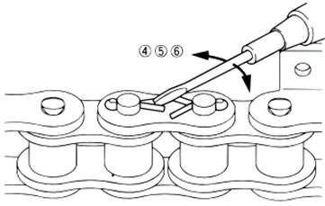
図25.
⚠ 注意
ドライバの先端が滑って、手などを突かないように十分注意をして作業を行ってください。
- (4)ドライバの先端を斜めに割ピンに差し込み、ドライバを左右に動かし、割ピンの脚を開きます。
- (5)この時に割ピンが、割ピン穴から抜けないように、割ピンの頭を押さえるときっちり仕上がります。
- (6)割ピンの脚の開き角度は前記のとおりです。
4. 倍速チェーン
1) クリップで継ぐ(RF2060以下のサイズ)
- (1)継手リンクの2本のピンを、内リンクのブシュに通した後で継手プレートの穴に通します。
- (2)クリップをピンの溝に確実に入れます。
2) 割ピンで継ぐ(RF2080の場合)
- (1)継手リンクの2本のピンを、内リンクのブシュに通した後で継手プレートの穴に通します。
- (2)割ピンをピンの穴に通し60°位に脚を開きます。
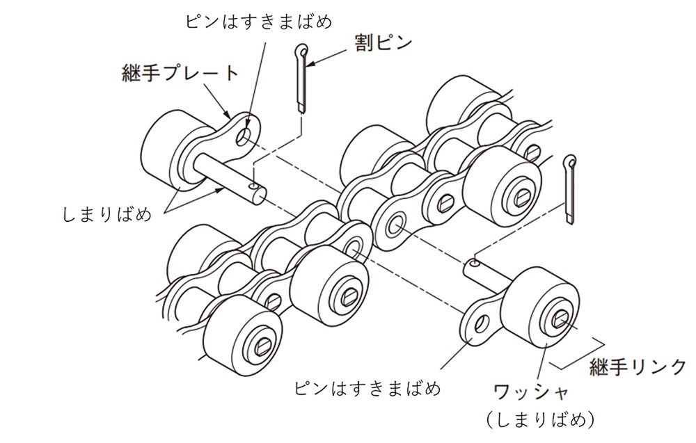
5. サイドローラ付チェーン
継手リンクを使ってチェーンを連結します。
1) サイドローラが千鳥形の継ぎ方
- (1)継手リンクの2本のピンを各々の内リンクの穴に入れ、さらにすきまばめの継手プレートに通します。
- (2)各々のピンに割ピンを入れ、割ピンの脚を約60°に開きます。
2) サイドローラが平行形の継ぎ方
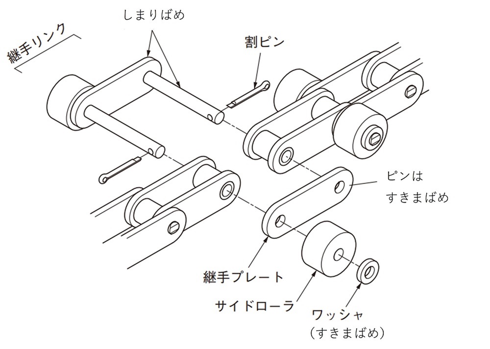
- (1)継手リンクの2本のピンを内リンクの穴に通し、すきまばめの継手プレートに通します。
- (2)図のようにピンの両端にサイドローラ付の場合は、サイドローラとワッシャをピンに通し、2ヵ所に割ピンを取付けます。割ピンの開脚角度は約60°です。
6. トップローラ付チェーン
- (1)連結は継手リンクで行います。
- (2)継手リンクの2本のピンを内リンクのブシュに通し、継手プレートの穴に通します。(継手プレートはすきまばめ)
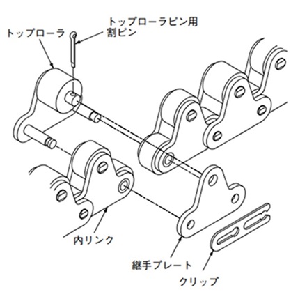
クリップ形継手リンク
割ピン形継手リンク
- (3)割ピンまたはクリップをピンに確実に取付けます。割ピンの脚は約60°に開きます。クリップの止め方は倍速チェーンの項に詳しく記しています。
トップローラ付チェーンの継手リンク
- 1. 継手リンクには2種類ありますので、継手リンクだけをご発注の際は注意してください。
- 2. 下記の1リンク毎トップローラ付と2リンク毎トップローラ付は、トップローラの外径が違います。寸法図も合わせてご覧ください。 (バイピッチトップローラ径は同一です。)
- 3. トップローラ以外のアタッチメントが継手リンクに付いている場合は、別途図面などで指示してください。(継手リンク記号:JL)
1リンク毎プラトップローラ付の場合
形番表示例
| RS40-1LTRPS | - | JL |
| | 本体チェーン |
| 継手リンク |
|
2リンク毎プラトップローラ付の場合
形番表示例
| RS40-2LTRP | - | JL |
| | 本体チェーン |
| 継手リンク |
|
