技術資料 小形コンベヤチェーン 選定
選定手順や注意事項等をご覧になりたい方は下記へお進みください。
製品シリーズの絞り込みや仮選定をご希望の方は
こちらをクリックしてください。
使用条件が決まっており詳細な選定をご希望の方は
こちらをクリックしてください。
フリーフローチェーンの選定
手順1. 搬送条件の確認
- (1)搬送物の種類、質量、寸法、数量(パレットも含む)
- (2)コンベヤ速度
- (3)コンベヤ長さ(アキュムレート部と搬送部の長さ)
- (4)雰囲気
手順2. チェーンタイプの選定
使用条件・雰囲気からチェーン本体およびローラの仕様を決定します。
手順3. チェーン品種の仮決定
チェーン張力の仮チェックを行います。
- SI単位:F = 9.80665×WT × f × Kv/1000
- 重力単位:F = WT × f × Kv
注)当カタログはSI単位と重力単位を併記しています。
重力単位で最大張力Fを計算する場合の重量(kgf)は質量(kg)と同一数値です。
- F:チェーンに作用する最大張力 kN {kgf}
- WT:チェーン以外の搬送物総質量 kg
- f:摩擦係数 f2(表8) + f3(表9)
- Kv:速度係数(表13)
チェーンを2本並列で使用する場合はチェーンの作用張力は均等になりません。
作用張力のアンバランスを考慮して、チェーンの最大許容張力(表14・15)がF × 0.6以上のチェーン形式・サイズを仮決定します。
小形コンベヤチェーン(ステンレス・エンプラ製※除く)の最大許容張力は、疲労限度を下限としております。
この値以下の荷重であれば、繰返し負荷をかけても小形コンベヤチェーンの破壊は起こりません。
※ステンレス製・エンプラ製 ピンとブシュ間の面圧を摩耗性能から想定し、最大許容張力を決定しています。
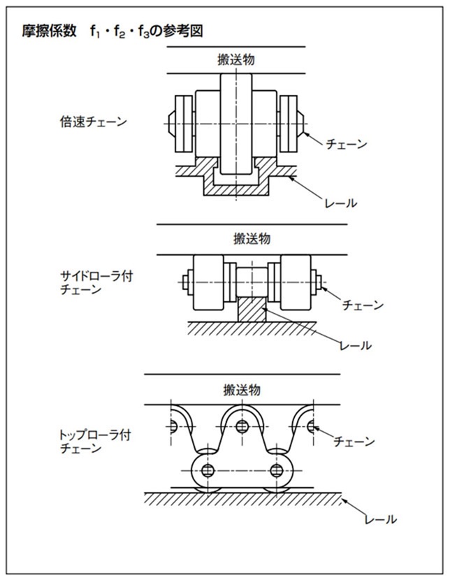
表7 f1:搬送時のチェーンとレールの摩擦係数
| チェーン品種 | チェーン本体のローラ | 潤滑(無) | 潤滑(有) | |
|---|---|---|---|---|
| 倍速チェーン | プラローラ | A・B・C・D UA・UB |
0.08 | - |
| スチールローラ | - | 0.05 | ||
| センタローラチェーン | スチールローラ | - | 0.08 | |
| サイドローラ付 および トップローラ付 チェーン |
スチール ローラ |
Sローラ | (0.21) | 0.14 |
| Rローラ | (0.12) | 0.08 | ||
| プラローラ | Sローラ | - | - | |
| Rローラ | 0.08 | - | ||
| プラコンビ | - | 0.25 | - | |
()内は参考値です。
表8 f2:アキュムレート時のチェーンと搬送物の摩擦係数
| チェーン品種 | 搬送ローラ | 潤滑(無) | 潤滑(有) |
|---|---|---|---|
| 倍速チェーン | A・C・UA | 0.10 | - |
| B・D・UB | 0.15 | - | |
| スチールローラ | - | 0.10 | |
| センタローラチェーン | スチールローラ | - | 0.06 |
| サイドローラ付 チェーン |
プラサイドローラ | 0.06 | - |
| プラブレーキ付サイドローラ | 0.20※ | - | |
| スチールサイドローラ | (0.09) | 0.06 | |
| トップローラ付 チェーン |
プラトップローラ | 0.06 | - |
| スチールトップローラ | (0.09) | 0.06 |
()内は参考値です。
注)プラブレーキサイドローラ1個当たりの摩擦係数を示します。ブレーキサイドローラがサイドローラ全数のおよそ1/3の場合にはこの摩擦係数は0.1となります。
(RFバイピッチはこちら、RS形はこちらのサイドローラの取付位置を参照ください)
表9 f3:アキュムレート時のチェーンとレールの摩擦係数
| チェーン品種 | チェーン本体のローラ | 潤滑(無) | 潤滑(有) | |
|---|---|---|---|---|
| 倍速チェーン | A・C・UA | 0.20 | - | |
| B・D・UB | 0.25 | - | ||
| スチールローラ | - | 0.10 | ||
| センタローラチェーン | スチールローラ | - | 0.10 | |
| サイドローラ付 および トップローラ付 チェーン |
スチール ローラ |
Sローラ | (0.21) | 0.14 |
| Rローラ | (0.12) | 0.08 | ||
| プラローラ | Sローラ | - | - | |
| Rローラ | 0.08 | - | ||
| プラコンビ | - | 0.25 | - | |
()内は参考値です。
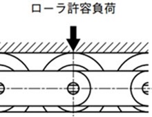
手順4. ローラの許容負荷の確認
潤滑状態での使用を前提とし、ローラ回転不良を生じない目安の値です。
ローラに作用する荷重は下記の値以下にしてください。スチールローラの値は潤滑状態のものです。
1. 倍速チェーン・センタローラチェーン
・RF2030~RF2080の場合
チェーン2条当たりの搬送許容負荷(パレットの長さ1m当たりの許容負荷)を示しています。
表10 ローラ許容負荷
| サイズ | チェーン本体のローラ | フレーム | ||
|---|---|---|---|---|
| アルミフレーム | スチールレール付 アルミフレーム |
|||
| RF2030 | プラローラ | A・B・C・D | 0.39 {40} | 0.78 {80} |
| UA・UB | 0.20 {20} | 0.20 {20} | ||
| スチールローラ | - | 1.57 {160} | ||
| RF2040 | プラローラ | 0.59 {60} | 1.18 {120} | |
| スチールローラ | - | 2.35 {240} | ||
| RF2050 | プラローラ | 0.78 {80} | 1.57 {160} | |
| スチールローラ | - | 3.14 {320} | ||
| RF2060 | プラローラ | 0.98 {100} | 1.96 {200} | |
| スチールローラ | - | 3.92 {400} | ||
| RF2080 | プラローラ | - | 2.94 {300} | |
| スチールローラ | - | 5.88 {600} | ||
2. サイドローラ付・トップローラ付チェーン
サイドローラ・トップローラとチェーン本体のローラと両方のローラ許容負荷を確認ください。
1) ローラ許容負荷
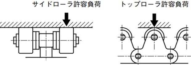
表11 ローラ許容負荷
| サイズ | サイドローラおよび 1列トップローラ |
2列トップローラ | ||
|---|---|---|---|---|
| プラローラ | スチールローラ | ステンレスローラ | スチールローラ | |
| RF2040・RS40 | 0.05 {5} | 0.15 {15} | 0.05 {5} | 0.29 {30} |
| RF2050・RS50 | 0.07 {7} | 0.20 {20} | 0.06 {6} | 0.39 {40} |
| RF2060・RS60 | 0.10 {10} | 0.29 {30} | 0.09 {9} | 0.59 {60} |
| RF2080・RS80 | 0.18 {18} | 0.54 {55} | 0.15 {15} | 1.08 {110} |
| RF2100・RS100 | 0.29 {30} | 0.78 {80} | 0.25 {25} | 1.57 {160} |
注)ラムダローラのローラ許容負荷はスチールローラと同等です。
2) チェーン本体のローラ許容負荷
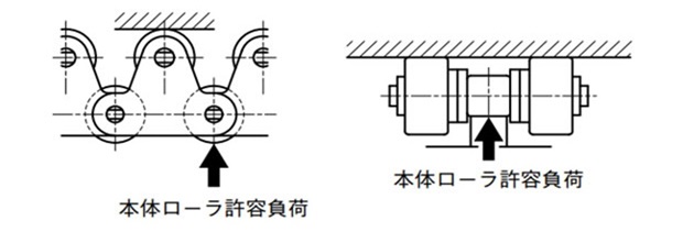
表12 チェーン本体のローラ許容負荷
| サイズ | スチールローラ | プラローラ | プラコンビ | ステンレスローラ | ||
|---|---|---|---|---|---|---|
| Rローラ | Sローラ | Rローラ | Rローラ | Sローラ | ||
| RF2040・RS40 | 0.64 {65} | 0.15 {15} | 0.20 {20} | 0.02 {2} | 0.20 {20} | 0.05 {5} |
| RF2050・RS50 | 0.98 {100} | 0.20 {20} | 0.29 {30} | 0.04 {4} | 0.29 {30} | 0.06 {6} |
| RF2060・RS60 | 1.57 {160} | 0.29 {30} | 0.49 {50} | 0.06 {6} | 0.49 {50} | 0.09 {9} |
| RF2080・RS80 | 2.65 {270} | 0.54 {55} | 0.88 {90} | - | 0.78 {80} | 0.15 {15} |
| RF2100・RS100 | 3.92 {400} | 0.78 {80} | 1.27 {130} | - | 1.18 {120} | 0.25 {25} |
注)
- 1. プラコンビはプラ内リンク1個当たりの許容負荷です。
- 2. ラムダチェーンはスチールローラと同じです。
- 3. 本体スチールRローラのガイドレールの材質は、S45C以上の高抗張力材を使用してください。
- 4. プラローラにはKV仕様を含みます。
手順5. チェーンに作用する張力(F)の計算
SI単位
F =
G
1000
× {(W1 + M) × L1 × f1 + W2 × L2 × f2
+ (W2 + M) × L2 × f3 + 1.1 × M × (L1 + L2) × f1}
kW = F・V 60 × 1 η
重力単位
F = (W1 + M) × L1 × f1 + W2 × L2 × f2 + (W2 + M) × L2 × f3
+ 1.1 × M × (L1 + L2) × f1
kW = F・V 6120 × 1 η
- F:チェーンに作用する最大張力:kN{kgf}
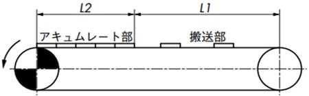
- L1:搬送部の長さ:m
- W1:搬送部の搬送物質量:kg/m
- L2:アキュムレート部の長さ:m
- W2:アキュムレート部の搬送物質量:kg/m
- f1:搬送部のチェーンとレールの摩擦係数
- f2:アキュムレート部のチェーンと搬送物の摩擦係数
- f3:アキュムレート部のチェーンとレールの摩擦係数
- M:チェーンの質量:kg/m
- kW:所要動力:kW
- V:チェーン速度:m/min
- η:駆動部の伝達機械効率
- G:重力加速度:9.80665m/s2
フリーフローコンベヤの場合は、一般にチェーンを2本並列で使用するため、チェーン質量は2本の質量とします。したがって、Fはチェーン2本に作用する最大張力です。
ただし、作用張力のアンバランスを考慮して、1本当たり0.6Fが作用するものとします。
手順6. チェーンサイズの決定
チェーン1本に作用する最大張力(0.6F)に表13の速度係数(Kv)を乗じ、次式を満足するチェーンを選定します。
0.6F × Kv ≦ チェーンの最大許容張力
小形コンベヤチェーン(ステンレス・エンプラ製※除く)の最大許容張力は、疲労限度を下限としております。
この値以下の荷重であれば、繰返し負荷をかけても小形コンベヤチェーンの破壊は起こりません。
※ステンレス製・エンプラ製 ピンとブシュ間の面圧を摩耗性能から想定し、最大許容張力を決定しています。
表13 速度係数(Kv)
| チェーン速度 m/min | 速度係数 (Kv) |
|---|---|
| 15以下 | 1.0 |
| 15~30 | 1.2 |
| 30~50 | 1.4 |
| 50~70 | 1.6 |
| 70~90 | 2.2 |
| 90~110 | 2.8 |
| 110~120 | 3.2 |
下記のチェーンの推奨速度は次のとおりです。
- 倍速チェーン:5 ~ 15m/min以下
- プラRローラ付チェーン:70m/min以下
- プラコンビチェーン:70m/min以下
表14 チェーンの最大許容張力(1)
| サイズ&ローラ形式 | チェーン本体仕様 | ローラの種類 | |
|---|---|---|---|
| A・C・UA | B・D・UB | ||
| RF2030VRP | 普通仕様 | 0.55 {56} | 0.27 {28} |
| HCP仕様 | |||
| ラムダ仕様 | |||
| SS仕様 | 0.27 {28} | ||
| RF2040VRP | 普通仕様 | 0.88 {90} | 0.44 {45} |
| HCP仕様 | |||
| ラムダ仕様 | |||
| SS仕様 | 0.44 {45} | ||
| RF2050VRP | 普通仕様 | 1.37 {140} | 0.69 {70} |
| HCP仕様 | |||
| ラムダ仕様 | |||
| SS仕様 | 0.69 {70} | ||
| RF2060VRP | 普通仕様 | 2.06 {210} | 1.03 {105} |
| HCP仕様 | |||
| ラムダ仕様 | |||
| SS仕様 | 1.03 {105} | ||
| RF2080VRP | 普通仕様 | 5.30 {540} | 2.65 {270} |
| HCP仕様 | |||
| ラムダ仕様 | |||
| SS仕様 | 2.65 {270} | ||
| サイズ&ローラ形式 | チェーン本体仕様 | ローラの種類 | |
|---|---|---|---|
| スチール仕様 (倍速チェーン) |
センタローラ (等速) |
||
| RF2030VR | 普通仕様 | 0.98 {100} | - |
| RF2040VR・CR | 普通仕様 | 1.57 {160} | 1.57 {160} |
| RF2050VR・CR | 普通仕様 | 2.45 {250} | 2.45 {250} |
| RF2060VR・CR | 普通仕様 | 3.73 {380} | 3.73 {380} |
| RF2080VR・CR | 普通仕様 | 5.30 {540} | 5.30 {540} |
表15 チェーンの最大許容張力(2)
| サイズ | チェーン品種 | ||||||
|---|---|---|---|---|---|---|---|
| サイドローラ付チェーン | 1列トップローラチェーン | ||||||
| スチール ローラ |
プラ Rローラ |
プラコンビ | ステンレス ローラ |
スチール ローラ |
プラ Rローラ |
ステンレス ローラ |
|
| RF2040・RS40 | 2.65 {270} | 0.44 {45} | 0.44 {45} | 0.69 {70} | 2.65 {270} | 0.44 {45} | 0.69 {70} |
| RF2050・RS50 | 4.31 {440} | 0.69 {70} | 0.69 {70} | 1.03 {105} | 4.31 {440} | 0.69 {70} | 1.03 {105} |
| RF2060・RS60 | 6.28 {640} | 1.03 {105} | 0.88 {90} | 1.57 {160} | 6.28 {640} | 1.03 {105} | 1.57 {160} |
| RF2080・RS80 | 10.7 {1090} | 1.77 {180} | - | 2.65 {270} | 10.7 {1090} | 1.77 {180} | 2.65 {270} |
| RF2100 | 17.1 {1740} | 2.55 {260} | - | 2.55 {260} | 17.1 {1740} | 2.55 {260} | 2.55 {260} |
| RS100 | 3.82 {390} | 3.82 {390} | |||||
注)
- 1. ラムダ仕様も上表のスチールローラと同じです。
- 2. 2列トップローラ付チェーンの最大許容張力は1列トップローラ付チェーンの1.7倍となります。ただしラムダ仕様の場合は1.4倍となります。
