技術資料 小形コンベヤチェーン 選定
選定手順や注意事項等をご覧になりたい方は下記へお進みください。
製品シリーズの絞り込みや仮選定をご希望の方は
こちらをクリックしてください。
使用条件が決まっており詳細な選定をご希望の方は
こちらをクリックしてください。
小形コンベヤチェーンの選定手順
コンベヤの種類、および容量によって、適当なチェーンサイズ、形式を選定します。コンベヤの使用条件によって種々な場合が考えられ、一概には決められない場合もありますが、一般に次の手順で行います。
1. 搬送条件の確認
2. チェーン品種の仮決定
3. ローラとアタッチメントの許容負荷の確認
4. チェーンに作用する最大張力の計算
5. チェーンサイズの決定
6. 間欠運転の場合のチェーン選定法
手順1. 搬送条件の確認
- 1. コンベヤの種類(スラットコンベヤ、バケットコンベヤなど)
- 2. 搬送方向(水平、傾斜、垂直搬送)
- 3. 搬送物の種類、質量、寸法
- 4. 搬送量、搬送間隔
- 5. コンベヤ速度
- 6. コンベヤ長さ
- 7. 潤滑の有無
- 8. 搬送の雰囲気(温度、腐食要因)
手順2. チェーン品種の仮決定
チェーンに作用する静的最大張力(F)を求めます。
SI単位 F(kN) = W × f1 × KV × G 1000
重力単位 F{kgf} = W × f1 × KV
W = コンベヤ上の搬送物総質量{重量} kg{kgf}
f1 = 摩擦係数(表3) KV = 速度係数(表4)
G = 9.80665m/s2
F(チェーンが並列のときは、F × 0.6)以上の最大許容張力を持った
チェーン形式・サイズを仮決定します。
小形コンベヤチェーン(ステンレス・エンプラ製※除く)の最大許容張力は、疲労限度を下限としております。
この値以下の荷重であれば、繰返し負荷をかけても小形コンベヤチェーンの破壊は起こりません。
※ステンレス製・エンプラ製 ピンとブシュ間の面圧を摩耗性能から想定し、最大許容張力を決定しています。
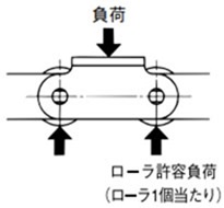
手順3. 許容負荷の確認
載荷方式のコンベヤなどでローラ、またはアタッチメントに作用する荷重は表1・表2の値以下にしてください。
表1 本体ローラの許容負荷
| サイズ | バイピッチ アタッチメント付RS形(普通仕様) ラムダ・長寿命ラムダ |
ステンレスローラ (SS, AS) |
プラローラ | プラローラ KV仕様 |
低騒音 プラローラ |
プラコンビ | |||
|---|---|---|---|---|---|---|---|---|---|
| Rローラ | Sローラ | Rローラ | Sローラ | Rローラ | Sローラ | Rローラ | Rローラ | ||
| RS25 | - | - | - | - | - | - | - | - | 0.005 {0.5} |
| RS35 | - | - | - | - | - | - | - | - | 0.015 {1.5} |
| RF2040・RS40 | 0.64 {65} | 0.15 {15} | 0.20 {20} | 0.05 {5} | 0.20 {20} | 0.02 {2} | 0.20 {20} | 0.14 {14} | 0.02 {2.0} |
| RF2050・RS50 | 0.98 {100} | 0.20 {20} | 0.29 {30} | 0.06 {6} | 0.29 {30} | 0.03 {3} | 0.29 {30} | 0.21 {21} | 0.04 {4.0} |
| RF2060・RS60 | 1.57 {160} | 0.29 {30} | 0.49 {50} | 0.09 {9} | 0.49 {50} | 0.05 {5} | 0.49 {50} | 0.34 {35} | 0.06 {6.0} |
| RF2080・RS80 | 2.65 {270} | 0.54 {55} | 0.78 {80} | 0.15 {15} | 0.88 {90} | 0.09 {9} | - | 0.62 {63} | - |
| RF2100・RS100 | 3.92 {400} | 0.78 {80} | 1.18 {120} | 0.25 {25} | 1.27 {130} | - | - | - | - |
| RF2120・RS120 | 5.88 {600} | 1.18 {120} | 1.77 {180} | 0.34 {35} | - | - | - | - | - |
| RS140 | - | 1.32 {135} | - | 0.39 {40} | - | - | - | - | - |
| RF2160・RS160 | 9.61 {980} | 1.91 {195} | 2.75 {280} | 0.54 {55} | - | - | - | - | - |
| BSアタッチメント付 | |
|---|---|
| サイズ | 普通仕様 |
| RF06B | 0.073 {7} |
| RS08B | 0.15 {15} |
| RS10B | 0.2 {20} |
| RS12B | 0.29 {30} |
| RS16B | 0.54 {55} |
| RS20B | 0.79 {81} |
| RS24B | 1.37 {140} |
本体ローラの許容負荷
注)
- 1. 潤滑状態での値です。バイピッチ、アタッチメント付RS形には、耐環境チェーン(NP・NEP仕様)を含みます。
- 2. プラコンビは、内リンクの下面を受けた場合の1個当たりの許容負荷です。
- 3. 普通仕様Rローラのガイドレールの材質は、S45C以上の高抗張力材をご使用ください。
- 4. ニードルブシュチェーン、ニードルケージチェーンについては製品情報ページをご参照ください。
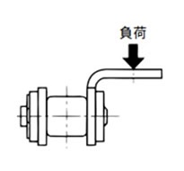
表2 Aアタッチメントの許容負荷
A形アタッチメントが許容できる垂直荷重です。
お客様で取付けられるアタッチメントの形状・構造によっては、Aアタッチメントを捩じる力が発生する場合が有りますので、その際にはお問合せください。
| バイピッチチェーン | RS形チェーン | ||||
|---|---|---|---|---|---|
| サイズ | バイピッチ注1 | ステンレス | サイズ | アタッチメント付注1 | ステンレス |
| RF2040 | 0.262 {26.7} | 0.108 {11.0} | RS25 | 0.028 {2.9} | 0.012 {1.2} |
| RF2050 | 0.455 {46.4} | 0.189 {19.3} | RS35 | 0.094 {9.6} | 0.036 {3.7} |
| RF2060 | 1.06 {108} | 0.419 {42.7} | RS40 | 0.130 {13.3} | 0.054 {5.5} |
| RF2080 | 1.67 {170} | 0.646 {65.9} | RS50 | 0.243 {24.8} | 0.101 {10.3} |
| RF2100 | 2.51 {256} | 1.15 {117} | RS60 | 0.376 {38.3} | 0.148 {15.1} |
| RF2120 | 3.68 {375} | 1.79 {183} | RS80 | 0.591 {60.3} | 0.233 {23.8} |
| RF2160 | 5.84 {596} | 3.13 {319} | RS100 | 0.933 {95.1} | 0.361 {36.8} |
| RS120 | 1.39 {142} | 0.629 {64.1} | |||
| RS140 | 1.82 {186} | 0.869 {88.6} | |||
| RS160 | 2.36 {241} | 1.19 {121} | |||
注)
- 1. 耐環境チェーン(NP・NEP仕様)を含みます。
- 2. ニードルブシュチェーン、ニードルケージチェーンについては製品情報ページをご参照ください。
| BSアタッチメント付形チェーン | |
|---|---|
| サイズ | 普通仕様 |
| RF06B | 0.09 {9} |
| RS08B | 0.2 {20} |
| RS10B | 0.13 {13} |
| RS12B | 0.21 {21} |
| RS16B | 1.18 {120} |
| RS20B | 0.97 {99} |
| RS24B | - |
- ・Aアタッチメントの1個が許容できる垂直負荷の作用点は、アタッチメントの取付穴の位置とします。
- ・Kアタッチメントは、Aアタッチメントの2倍となります。
- ・ローラの許容負荷を越えないように注意してください。
手順4. チェーンに作用する最大張力(F)の計算
カタログではSI単位と重力単位を併記しています。重力単位で最大張力を計算する場合の重量(kgf)は、質量(kg)と同一の数値です。
- F = チェーンに作用する静的最大張力:kN{kgf}
- V = 搬送速度(チェーン速度):m/min
- H = スプロケット中心距離(垂直方向):m
- L = スプロケット中心距離(水平方向):m
- C = スプロケット中心距離:m
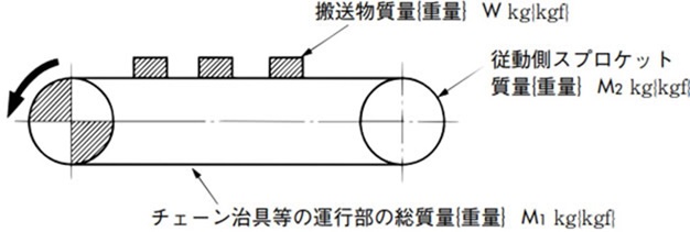
- M = 運行部の質量{重量}:チェーン※、バケット、エプロンなどの質量{重量}:kg/m{kgf/m}
- W = コンベヤ上の搬送物総質量{重量}の最大値:kg{kgf}
カズ物の時:W = C 積載間隔 × 搬送物質量{重量} - kW = 所要動力
- f1 = チェーンとガイドレールとの摩擦係数(表3)
- η = 駆動部の伝動機械効率
- G = 重力加速度:9.80665m/s2
※チェーンを2本並列で使用する場合は、2条分のチェーン重量となります。
※正逆運転を頻繁に行う場合はテークアップによりチェーンのたるみを取る必要がありますので、下記計算式とは異なります。
テークアップでチェーンのたるみを取る場合は、こちらのQ&A6の計算式をご使用ください。
表3-1 f1:本体チェーンのローラがレール上を転がる時の摩擦係数
| ローラ 区分 |
スチールローラ | ラムダ チェーン |
プラローラ注 | 低騒音 プラローラ |
ニードルブシュ チェーン |
|
|---|---|---|---|---|---|---|
| 潤滑(無) | 潤滑(有) | 潤滑(無) | 潤滑(無) | |||
| Rローラ | 0.12 | 0.08 | 0.08 | 0.08 | 0.1 | 0.21 |
| Sローラ | 0.21 | 0.14 | 0.14 | - | - | - |
注)プラローラにはKV仕様を含みます。
表3-2 f1:チェーンのプレートがレール上を滑る時の摩擦係数
| スチールプレート | プラコンビ | |
|---|---|---|
| 潤滑(無) | 潤滑(有) | |
| 0.3 | 0.2 | 0.25 |
計算式
| SI単位 | {重力単位} |
|---|---|
|
水平搬送 搬送物を乗せて運ぶ場合 F = (W + 2.1 × M × C) × f1 × G 1000 kW = F × V 6120 × 1 η 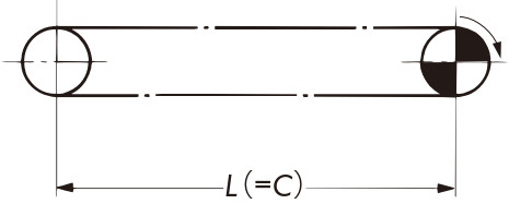
F = (W + 2.1 × M × C) × f1 kW = F × V 6120 × 1 η |
|
|
垂直搬送 F = (W + M × C) × G 1000 kW = W × V 60 × G 1000 × 1 η 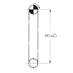
F = W + M × C kW = W × V 6120 × 1 η |
|
|
傾斜搬送※ 搬送物を乗せて運ぶ場合 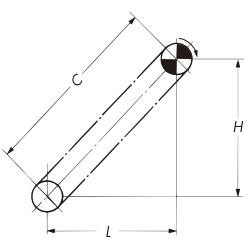
F = (W + M × C) L × f1 + H C + 1.1 × M × (L × f1 - H) × G 1000 kW = V 60 F - M × (H - L × f1) G 1000 × 1 η F = (W + M × C) L × f1 + H C + 1.1 × M × (L × f1 - H) kW = V 6120 F - M × (H - L × f1) × 1 η 注)※印のFの式でL × f1 - H < 0 のときは、L × f1 - H = 0とします。また、kWの式でH - L × f1 < 0 のときは、H - L × f1 = 0とします。 |
|
|
水平・傾斜搬送※ 搬送物を乗せて運ぶ場合 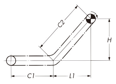
F =
(
W
C1 + C2
+ 2.1 × M) C1 × f1+
(
W
C1 + C2
+ M) × (L1 × f1 + H)
kW = V 60 F - M × (H - L1 × f1) G 1000 × 1 η F =
(
W
C1 + C2
+ 2.1 × M) × C1 × f1+
(
W
C1 + C2
+ M) × (L1 × f1 + H)
kW = V 6120 F - M × (H - L1 × f1) × 1 η 注)※印のFの式でL1 × f1 - H < 0のときは、L1 × f1 - H = 0とします。また、kWの式でH-L1×f1 < 0のときは、H - L1 × f1 = 0とします。 |
|
手順5. チェーンサイズの決定
チェーンに作用する最大張力(F)に表4の速度係数(KV)を乗じ、次式を満足するチェーンを選定します。
F × KV ≦ チェーンの最大許容張力
表4 速度係数(KV)
| チェーン速度 m/min | 速度係数 (Kv) |
|---|---|
| 15以下 | 1.0 |
| 15~30 | 1.2 |
| 30~50 | 1.4 |
| 50~70 | 1.6 |
| 70~90 | 2.2 |
| 90~110 | 2.8 |
| 110~120 | 3.2 |
下記のチェーンの推奨速度は次のとおりです。
|
30m/min以下 |
|
70m/min以下 |
表5 小形コンベヤチェーンの強度(単位:kN{kgf})

| サイズ | 汎用チェーン | ラムダチェーン 長寿命ラムダチェーン |
|---|---|---|
| RF2040 | 2.65 {270} | 2.65 {270} |
| RF2050 | 4.31 {440} | 4.31 {440} |
| RF2060 | 6.28 {640} | 6.28 {640} |
| RF2080 | 10.7 {1090} | 10.7 {1090} |
| RF2100 | 17.1 {1740} | 17.1 {1740} |
| RF2120 | 23.9 {2440} | 23.9 {2440} |
| RF2160 | 40.9 {4170} | - |
| サイズ | ステンレスバイピッチ | コーティングバイピッチ | |||||
|---|---|---|---|---|---|---|---|
| SS仕様 | HS仕様 | AS仕様 | NS仕様 | LSK仕様 | NP仕様 | NEP仕様 | |
| RF2040 | 0.69 {70} | 1.19 {121} | 0.69 {70} | 0.44 {45} | 0.44 {45} | 2.65 {270} | 2.65 {270} |
| RF2050 | 1.03 {105} | 1.85 {189} | 1.03 {105} | 0.69 {70} | 0.69 {70} | 4.31 {440} | 4.31 {440} |
| RF2060 | 1.57 {160} | 2.78 {283} | 1.57 {160} | 1.03 {105} | 1.03 {105} | 6.28 {640} | 6.28 {640} |
| RF2080 | 2.65 {270} | 4.77 {486} | 2.65 {270} | 1.77 {180} | - | 10.7 {1090} | 10.7 {1090} |
| RF2100 | 2.55 {260} | - | - | - | - | 17.1 {1740} | 17.1 {1740} |
| RF2120 | 3.82 {390} | - | - | - | - | 23.9 {2440} | - |
| RF2160 | 6.37 {650} | - | - | - | - | 40.9 {4170} | - |
| サイズ | 汎用シリーズ | 低騒音シリーズ | 耐熱仕様 | |||||
|---|---|---|---|---|---|---|---|---|
| 普通仕様 | NP仕様 | SS仕様 | SPローラ | 普通仕様 | NP仕様 | SS仕様 | ||
| RF2040 | 0.44 {45} | 0.44 {45} | 0.44 {45} | 0.23 {23} | 0.44 {45} | 0.44 {45} | 0.44 {45} | 0.44 {45} |
| RF2050 | 0.69 {70} | 0.69 {70} | 0.69 {70} | 0.34 {34} | 0.69 {70} | 0.69 {70} | 0.69 {70} | 0.69 {70} |
| RF2060 | 1.03 {105} | 1.03 {105} | 1.03 {105} | 0.54 {55} | 1.03 {105} | 1.03 {105} | 1.03 {105} | 1.03 {105} |
| RF2080 | 1.77 {180} | 1.77 {180} | 1.77 {180} | 0.88 {89} | 1.77 {180} | 1.77 {180} | 1.77 {180} | - |
| RF2100 | 2.55 {260} | 2.55 {260} | 2.55 {260} | - | - | - | - | - |
| サイズ | 汎用仕様 | LMC仕様 | NP仕様 | SS仕様 |
|---|---|---|---|---|
| RF2040 | 1.77 {180} | 1.47 {150} | 1.77 {180} | 0.44 {45} |
| RF2050 | 3.14 {320} | 2.55 {260} | 3.14 {320} | 0.69 {70} |
| RF2060 | 4.22 {430} | 3.43 {350} | 4.22 {430} | 1.03 {105} |
| RF2080 | 7.65 {780} | 6.18 {630} | 7.65 {780} | 1.77 {180} |
| サイズ | 汎用仕様 |
|---|---|
| RF2040 | 1.86 {190} |
| RF2050 | 2.84 {290} |
| RF2060 | 4.02 {410} |
| RF2080 | 6.96 {710} |
間欠搬送チェーン
| サイズ | 普通仕様 | 高精度仕様 | ステンレス仕様 |
|---|---|---|---|
| RF2040 | 0.78 {80} | 0.78 {80} | 0.44 {45} |
| RF2050 | 1.27 {130} | 1.27 {130} | 0.69 {70} |
| RF2060 | 1.77 {180} | 1.77 {180} | 1.03 {105} |
| RF2080 | 2.94 {300} | 2.94 {300} | 1.77 {180} |
| サイズ | 最大許容張力 |
|---|---|
| RF2040 | 0.45 {45} |
| RF2050 | 0.69 {70} |
| RF2060 | 1.03 {105} |
| RF2080 | 1.77 {180} |
| サイズ | 最大許容張力 |
|---|---|
| BCM12.5-9 | 0.3 {30} |
| BCM15-9 | 0.3 {30} |
| サイズ | 最大許容張力 |
|---|---|
| BC050 | 0.49 {50} |
| BC075 | 0.69 {70} |
| BC100 | 0.69 {70} |
| BC150 | 1.27 {130} |
| サイズ | 汎用チェーン | ラムダチェーン | 長寿命ラムダチェーン |
|---|---|---|---|
| RS25 | 0.64 {65} | - | - |
| RS35 | 1.52 {155} | 1.52 {155} | - |
| RS40 | 2.65 {270} | 2.65 {270} | 2.65 {270} |
| RS50 | 4.31 {440} | 4.31 {440} | 4.31 {440} |
| RS60 | 6.28 {640} | 6.28 {640} | 6.28 {640} |
| RS80 | 10.7 {1090} | 10.7 {1090} | 10.7 {1090} |
| RS100 | 17.1 {1740} | 17.1 {1740} | 17.1 {1740} |
| RS120 | 23.9 {2440} | 23.9 {2440} | - |
| RS140 | 32.4 {3300} | 32.4 {3300} | - |
| RS160 | 40.9 {4170} | - | - |
| サイズ | ステンレスアタッチメント付RS形チェーン | コーティングアタッチメント付RS形チェーン | プラコンビ | プラローラ チェーン |
|||||
|---|---|---|---|---|---|---|---|---|---|
| SS仕様 | HS仕様 | AS仕様 | NS仕様 | LSK仕様 (ステンレスローラ) |
NP仕様 | NEP仕様 | SPローラ | ||
| RS25 | 0.12 {12} | - | - | 0.12 {12} | - | 0.64 {65} | - | 0.08 {8} | - |
| RS35 | 0.26 {27} | - | - | 0.26 {27} | - | 1.52 {155} | - | 0.18 {18} | - |
| RS40 | 0.69 {70} | 1.19 {121} | 0.69 {70} | 0.44 {45} | 0.44 {045} | 2.65 {270} | 2.65 {270} | 0.44 {45} | 0.23 {23} |
| RS50 | 1.03 {105} | 1.85 {189} | 1.03 {105} | 0.69 {70} | 0.69 {070} | 4.31 {440} | 4.31 {440} | 0.69 {70} | 0.34 {34} |
| RS60 | 1.57 {160} | 2.78 {283} | 1.57 {160} | 1.03 {105} | 1.03 {105} | 6.28 {640} | 6.28 {640} | 0.88 {90} | 0.54 {55} |
| RS80 | 2.65 {270} | 4.77 {486} | 2.65 {270} | 1.77 {180} | - | 10.7 {1090} | 10.7 {1090} | - | 0.88 {89} |
| RS100 | 3.82 {390} | - | - | - | - | 17.1 {1740} | 17.1 {1740} | - | - |
| RS120 | 3.82 {390} | - | - | - | - | 23.9 {2440} | - | - | - |
| RS140 | 4.61 {470} | - | - | - | - | 32.4 {3300} | - | - | - |
| RS160 | 6.37 {650} | - | - | - | - | 40.9 {4170} | - | - | - |
| サイズ | 汎用仕様 | ラムダ仕様 | NP仕様 | SS仕様 |
|---|---|---|---|---|
| RS40 | 1.77 {180} | 1.47 {150} | 1.77 {180} | 0.44 {45} |
| RS50 | 3.14 {320} | 2.55 {260} | 3.14 {320} | 0.69 {70} |
| RS60 | 4.22 {430} | 3.43 {350} | 4.22 {430} | 1.03 {105} |
| RS80 | 7.65 {780} | 6.18 {630} | 7.65 {780} | 1.77 {180} |
| サイズ | 汎用仕様 |
|---|---|
| RS40 | 1.86 {190} |
| RS50 | 2.84 {290} |
| RS60 | 4.02 {410} |
| RS80 | 6.96 {710} |
注)
- 1. SS仕様、NS仕様については、出荷前の塗油を行っておりません。水中もしくは、水がかかる雰囲気以外でご使用になる場合は、ご使用前に必ず給油をお願いします。
- 2. 給油なしでご使用になった場合、早期にチェーンが屈曲不良を起こす可能性があります。
- 3. 最大許容張力は、給油条件下(水潤滑含む)での値です。
手順6. 間欠運転の場合のチェーンの選定法
インデキシング装置などを用いて、間欠運転でチェーンを使用する場合には、チェーンに作用する張力は、一般のチェーンの選定(摩擦力に基づく張力F)に加えて、慣性による付加張力F1を考慮する必要があります。
付加張力F1は、一般にF1 = mαによって求められます。この式を基本に計算手順を説明します。
- m = 従動側の総質量(kg)
- α = 最大加速度(m/s2)
| SI単位 | {重力単位} | ||||||||
|---|---|---|---|---|---|---|---|---|---|
|
|||||||||
|
1) 従動側の総質量mを求めます。 m = W + M1 + 1 2 M2 注) 1 2 M2:スプロケットの慣性力をチェーンに換算した概略値です。 |
|||||||||
|
2) 最大加速度α(m/s2)と上式より慣性による付加張力をF1=mαによって求めます。 例えば、カム式のインデックス装置を用いた場合、最大加速度αは、
カム曲線に応じたAmの値を用いてください。
詳細は、インデキシングメーカー各社にご確認ください |
|||||||||
|
3) 慣性による付加張力を考慮した全作用張力FΣを求めます。 FΣ = F + F1/1000 F:摩擦力に基づくチェーン張力(kN) 3) 慣性による付加張力を考慮した全作用張力FΣを求めます。 FΣ = F + F1/G F:摩擦力に基づくチェーン張力(kN) G:重力加速度9.80665(m/s2) |
|||||||||
|
4) チェーンサイズの決定 FΣKv ≦ チェーンの最大許容張力 Kv:速度係数(表4) |
|||||||||
|
5) チェーンのローラ許容負荷のチェックも行ってください。 ×
(ドラッグで移動できます)
潤滑状態での使用を前提とし、ローラ回転不良を生じない目安の値です。 |
|||||||||
