技術資料 ドライブチェーン ドライブチェーンとは
ローラチェーンの構造
基本構造

[クリックで拡大]
プレートは伝動中にローラチェーンにかかる張力を受け持つメンバです。この張力は通常は繰返し荷重ですが時には衝撃を伴う場合もあります。したがって、プレートには単に静的な抗張力だけではなく、疲れ強さ・衝撃強さが高く、動的にも強靭であるものであることが要求されます。
ピンはプレートを介してせん断と曲げを受けると同時に、ローラチェーンが屈曲してスプロケットと噛みあう際、ブシュと共に軸受部を構成するものです。したがって、せん断強さ・曲げ強さ・靭性の他に耐摩耗性が必要です。
ブシュは各部品を介して複雑な力を受けますが、特にスプロケットと噛み合う際に、ローラを介して繰返し衝撃荷重を受けますので、衝撃疲労強さが大きくなければなりません。また、ピンの相手となって軸受の作用をしますので耐摩耗性も要求されます。
ローラはローラチェーンがスプロケットに噛込むとき、前歯との衝突により繰返し衝撃荷重を受けます。また、噛み合った後、張力の大きさによって歯との噛合いの平衡位置が変化しますので、歯とブシュに挟まれながら歯面を移動し圧縮荷重と摩擦力を受けます。従って、衝撃疲労強さ・耐圧縮強さ・耐摩耗性が必要です。
注)RS15、RS25、RS35およびRS11-SSにはローラは付いていません。
2個のブシュが2枚の内プレートに圧入され、ブシュの外側にローラが回転できるようにはめられています。これは単列でも多列でも同じものを使います。
外リンクは、2本のピンが2枚の外プレートに圧入されています。多列ローラチェーンの場合は、外リンクに中間プレートが加わります。RSローラチェーンの中間プレートはすきまばめ(※1)、スーパチェーンはしまりばめ(※2)です。
| 基本3寸法 | ※1 すきまばめ | ※2 しまりばめ | ||
|---|---|---|---|---|
| ピッチ、ローラ径、内リンク内幅をローラチェーンの基本3寸法といいます。 この寸法が同一のときは、ローラチェーンとスプロケットは寸法的には互換性があります。 |
軸と穴を組み合わせたときに、常にスキマができるはめあい。穴の公差域が完全に軸(ピン、またはブシュ)の公差軸の上側にあるはめあい。 | 軸と穴を組合せたときに、常に締めしろができるはめあい。 穴の公差域が完全に軸(ピン、またはブシュ)の公差域の下側にあるはめあい。 |
連結部品
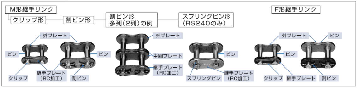
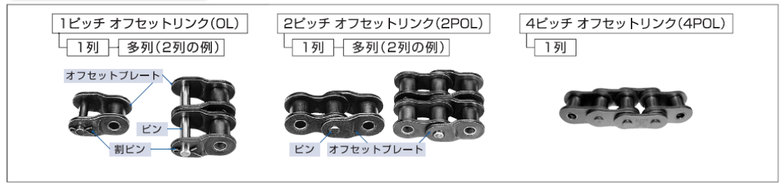
ローラチェーンは、普通多くのリンクが連結されエンドレス、または端末を固定して使用されますが、いずれも継手リンク(吊り下げ用などには専用継手リンク)が必要です。また、ローラチェーンが奇数リンクになる場合は、オフセットリンクが使用できますが、極力偶数リンクになる設計をしてください。
[クリックで拡大]
| チェーン品種 | 継手リンク名称 | ピンと 継手プレートの はめあい |
継手プレートの 止め方式 |
注意事項 |
|---|---|---|---|---|
| RSローラチェーン | M形継手リンク | すきまばめ | クリップ 割りピン スプリングピン |
|
| F形継手リンク | しまりばめ | クリップ・割りピン スプリングピン Tピン |
||
| ラムダチェーン | M形継手リンク | すきまばめ | クリップ 割りピン |
|
| スーパチェーン スーパHチェーン |
M形継手リンク | すきまばめ | スプリングピン |
|
| F形継手リンク | しまりばめ | スプリングピン |
|
|
| ウルトラスーパチェーン | F形継手リンク | しまりばめ | スプリングピン |
|
| 強力チェーン | M形継手リンク | すきまばめ | 割りピン スプリングピン |
|
| F形継手リンク | しまりばめ | 割りピン スプリングピン |
|
|
| カタログ記載 その他のローラチェーン |
M形継手リンク | すきまばめ | クリップ・割りピン スプリングピン Tピン・Zピン |
|
| 注) | |
| 1. | リングコイン(RC)加工とは、つばき独自の加工で継手プレートのピン穴にそって、塑性変形部を設けることで、穴周辺に残留応力を発生させることを目的としています。すきまばめでも強度低下を起こすことなく、本体チェーンと同一の強度でご使用いただけます。 |

リングコイン加工
[クリックで拡大]
| 注) | |
| 1. | オフセットリンクの適用ローラチェーン品種およびサイズは寸法図をご覧ください。 |
| 2. | オフセットリンクは本体チェーンに比べ伝動能力、最大許容張力が低下する場合があります。 |
