リニパワージャッキ簡易選定ツール
お客様のご使用条件に基づき、リニパワージャッキの選定計算を実施します。
対象品種
リニパワージャッキ JWB(ボールネジタイプ)
リニパワージャッキ JWH(ハイリードボールネジタイプ)
リニパワージャッキ JWM(台形ネジタイプ)
対象品種
リニパワージャッキ JWB(ボールネジタイプ)
リニパワージャッキ JWH(ハイリードボールネジタイプ)
リニパワージャッキ JWM(台形ネジタイプ)
コンテンツの利用について
- つばき産業用機械製品 情報サイト リニパワージャッキ簡易選定ツール(以下、「本ツール」といいます」)をご利用いただくにあたって、以下のご利用上の注意事項・免責事項を必ずお読みいただき、すべての内容に同意していただける場合のみご利用ください。
- 同意いただけない場合は、本ツールのご利用をお控えください。
ご利用上の注意事項 ・ 免責事項
選定計算 リニパワージャッキ
- ・ご要求の仕様に見合う形番を選定いたします。
- ・選定条件などをご入力後、画面最下部の判定ボタンをクリックしてください。
- ・ジャッキ1台においての選定計算ソフトです。
複数台数での選定におきましては、[STEP1 リニパワージャッキの選定 2.ジャッキ1台当たりの荷重Wの算出]をご参照ください。 - ・ジャッキ連動運転・周辺機器選定サービス
ジャッキ連動システムにおいて、リニパワージャッキだけでなく、ギヤボックス・カップリング・駆動部を含めて
選定、提案させていただきます。見積図面・レイアウト図の作成もいたしますので、是非ご利用ください。
選定条件を入力
選定条件を入力してください。
| 昇降荷重(最大) | W0 = | [kN] | [kgf] |
表1 使用係数 sf
注) 上記使用係数表は一般的な目安です。使用条件を考慮して決定ください。 |
||||||||||||
| 昇降荷重(最小) | W1 = | [kN] | [kgf] | |||||||||||||
| 使用係数 | Sf = | |||||||||||||||
| 座屈強度確認荷重 | W2 = | [kN] | [kgf] | |||||||||||||
| 希望昇降速度 | V' = | [m/min] | [mm/s] | |||||||||||||
| ストローク | ST0 = | [mm] | ||||||||||||||
| 実ストローク | ST = | [mm] | ||||||||||||||
| 運転頻度 | [往復/Hr]× [Hr/日]× [日/年] | |||||||||||||||
リニパワージャッキ仕様決定
リニパワージャッキの仕様を選択してください。
| JW | M | 050 | U | S | H | 10 | U |
| | シリーズ名 リニパワー ジャッキ |
| | | | | | | | | | | | | | |
| 基本容量 002:1.96kN{0.2tf} 005:4.90kN{0.5tf} 010:9.80kN{1tf} 025:24.5kN{2.5tf} 050:49.0kN{5tf} 100:98.0kN{10tf} 150:147kN{15tf} 200:196kN{20tf} 300:294kN{30tf} 500:490kN{50tf} 750:735kN{75tf} 1000:980kN{100tf} |
| | | | | | | | | | | | | | |
| | | | | | | | |
| ウォーム減速比 L、H 実際の減速比は 詳細情報を ご参照ください。 |
| 称呼ストローク 1:100mm 2:200mm 3:300mm 4:400mm 5:500mm 6:600mm 8:800mm 10:1000mm 12:1200mm 15:1500mm 20:2000mm |
| フランジ取付方向 ※トラベリングナット仕様の 場合のみ表記必要 |
| ネジ仕様 S:基本形 M:回り止め仕様 R:トラベリングナット仕様 |
|||||||
| ネジ種類 M:台形ネジ B:ボールネジ H:ハイリードボールネジ |
取付形状 U:押上用 D:吊下用 |
注) | ハイリードボールネジタイプ(ネジ種類:H)の 回り止め仕様(ネジ仕様:M)は見積り品となります。 ご使用条件をご連絡ください。 |
||||
| ネジ種類 | 基本容量 | ネジ仕様・取付形状 | ウォーム減速比 | フランジ取付方向 | 先端金具 | ジャバラ | クレビス金具 |
※基本容量300以上(294kN以上)のトラベリングナット仕様は、特殊品として製作可能です。詳しくはお問い合わせください。
※トラベリングナット仕様のジャバラ付きは都度見積もり品となります。詳しくはお問い合わせください。
※トラベリングナット仕様は、両端クレビス支持による据付ができません。
| ・センサー系オプション | ・入力系オプション | |||
| カウンターLS | 内部LS | ポテンショメータ | エンコーダ | モータ |
ジャッキ形番
| 基本容量 | [kN] | 総合効率 ηJ | |||
| ネジ谷底径 d | [mm] | 最大許容入力容量 | [kW] | ||
| ネジリード L | [m] | 許容無負荷空転トルク T0 | [N・m] | ||
| ウォーム速比 R | 許容入力軸トルク | [N・m] |
判定:
実速度の確認
モータ回転速度、実際の総減速比を入力してください。
| モータ回転速度 | Nm = | [r/min] |
| 必要入力回転速度 | N' = V'/L×R = | [r/min] |
| 必要減速比 | i' = Nm/N' = |
| 50Hz | 1500 r/min |
| 60Hz | 1800 r/min |
| 実際の総減速比 | i = | (ジャッキ入力軸から駆動モータまでの総減速比を入力) |
| 実昇降速度 | V = Nm×L/(i×R) = | [m/min] |
| [mm/s] |
諸元
| 必要入力軸トルク | T = W0×Sf×1000×L/(2π×R×ηJ)+T0 | = | [N・m] | |
| 必要逆転トルク(参考値) | T' = W0×Sf×1000×L×ηJ/(2π×R)-T0 | = | [N・m] | |
| 入力回転速度 | N = V/L×R | = | [r/min] | |
| 必要入力容量 | P = T×N/9550 | = | [kW] | |
| 入力軸慣性モーメント | IJ = W0×1000/g×{L/(2π×R)}2 | = | [kg・m2] |
判定:
座屈強度確認
据え付け状態を選択してください。
| 据え付け状態 |
※トラベリングナット仕様は両端クレビス支持を選択できません。 |
||
| 支持係数 | m = | ||
| 作用点間距離 | L1 = | [mm] | |
| 座屈強度 | PCR = m×(d2/L1)2/1000 = | [kN] | |
| 座屈安全率 | SF = PCR/(W2×Sf) = | (>=4) | |
据え付け状態 [クリックで拡大]
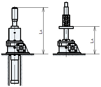
ベース固定-軸端フリー
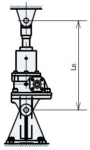
両端クレビス支持

ベース固定-軸端支持
| 基準距離 | ストローク | 金具寸度 | クレビス寸度 |
判定:
許容ネジ軸回転速度確認(トラベリングナットのみ)
使用頻度確認
| 使用時間 | ts = ST/(V×1000) = | [min] | |
| 負荷時間率(%ED) | %ED = [往復/Hr]×2×使用時間×100/60 = | [%ED] |
判定:
期待寿命計算(台形ネジタイプ)
| 年間総走行距離 | Ly = ST×2×[往復/Hr]×[Hr/日]×[日/年]×10-6 = | [km] |
| 期待寿命 | Z = (JWM050以下:5km, JWM100以上:1km)/Ly = | [年] |
期待寿命計算(ボールネジタイプ)
| 等価荷重 | PE = (W0×Sf×2+W1)/3 = | [kN] |
| ボールネジ動負荷容量 | C = | [kN] |
| 短ストローク補正係数 | fs = | |
| 運転条件係数 | fd = | |
| 焼入硬度補正係数 | fh = | |
| 寿命補正係数 | f1 = (PE×fd)/(C×fh×fs) = | |
| B10寿命総走行距離 | L10 = 250/f13 = | [km] |
| 年間総走行距離 | Ly = ST×2×[往復/Hr]×[Hr/日]×[日/年]×10-6 = | [km] |
| 期待寿命 | Z = L10/Ly = | [年] |
期待寿命計算(ハイリードボールネジタイプ)
ハイリードタイプの期待寿命計算につきましては、別途お問い合わせください。
選定結果
形番
:
必要入力容量
:
[kW]
減速比
:
都度見積品です。詳しくはお問い合わせください。
<注意>
本選定は理論計算値に基づいて選定を行ったもので、選定結果を保証するものではありません。
本選定の計算式を十分にご理解いただいた上で、計算結果に余裕を見込むなどして、
最終的な使用機器の決定は、お客様にてご判断くださいますようお願い致します。
