技術資料 高速リフタ リフトマスタ 取扱
運転・点検手順
ここでは、リフトマスタに関する一般的取扱いについて記載しています。
詳細につきましては、製品に同梱しています取扱説明書をご参照ください。
運転
- ・リフトマスタは、許容荷重、許容オーバハングロードおよび許容昇降速度を必ず守ってお使いください。
これを超えると本体が破損したり、搬送物が落下するなどのおそれがあります。 - ・いかなる場合でも惰行も含めてストロークを逸脱する範囲では絶対に使用しないでください。逸脱すると装置が破損するおそれがあります。リフタには、いかなるときでも衝撃を与えないでください。
- ・ネジ、可動部、検出部などには、粉塵や切粉などの異物が付着もしくは混入しないようにしてください。これらは摩耗を促進し、ネジ寿命の低下や、可動部の破損など重大な事故に繋がります。リフトマスタ本体に異物が侵入しないように必ず対策してください。
さらにリフトマスタの周囲に安全柵を設け、昇降物下の空間に立ち入ることができないようにしてください。 - ・停止時には負荷が落下しないよう、必ずモータの保持ブレーキが作動するようにシーケンス回路を設計してください。
- ・いかなる場合も当て止めは、行わないでください。当て止めを行いますと製品内部に重大な損傷を起こすおそれがあります。
- ・リフトマスタは、圧縮荷重が作用する要件のみの使用方法でご使用ください。
| ⚠ 警告 |
|
|---|
保守・点検
1. カバーの取外し
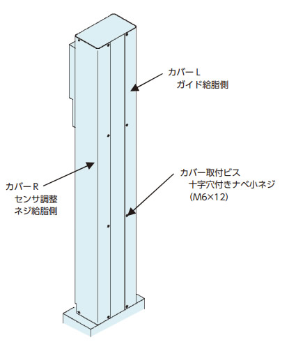
上下限センサの位置変更およびネジシャフトへの給脂の際にはカバーR、ガイドへの給脂の際にはカバーLの取外しが必要です。
カバー取外しの際には、取付ビス(十字穴付きナベ小ネジM6×12)を外してからカバーを取外してください。
※下記図は参考図となります。実際の外形は納品図をご参照ください。
2. 給脂
(ネジ部)
最大ストロークまで動かし、古いグリースを拭き取った後、グリースガンおよびブラシ等で直接ネジ軸に塗布してください。
(ガイド部)
グリースニップルから給脂します。
古いグリースが排出されるまで、十分に新しいグリースを給脂します。
給脂後は慣らし運転を実施し、余分なグリースは除去してから運転を開始してください。
<給脂箇所参考図>
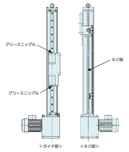
※上記図は参考図となります。実際の外形は納品図をご参照ください。
| 項目 | 使用区分 | |||
|---|---|---|---|---|
| ネジ部 | ガイド部 | |||
| 使用グリース (出荷時使用グリース) |
ダフニーエポネックス SR No.2 (出光興産株式会社 製) |
|||
| 給脂サイクル | 台形ネジ | ボールネジ | 3カ月 | |
| 使用頻度50~100回/日 | 1カ月 | 3カ月 | ||
| 使用頻度10~50回/日 | 3カ月 | 3カ月 | ||
| 使用頻度1~10回/日 | 6カ月 | 6カ月 | ||
| 給脂量 | 10~15g (ストローク100mmあたり) |
LME200,500 | 4.5~6.5g | |
| LME1000 | 9.0~13.5g | |||
3. 三相モータ(ハイポイドモートル)の保守・点検
ハイポイドモートルの保守・点検については、添付のハイポイドモートル取扱説明書をご参照ください。
<作業手順>
- (1) 本作業を始める前には必ず電源を落としてください。
- (2) リフトマスタ本体とお客様装置を切離し、リフトマスタ本体に負荷が掛からない状態としてください。その際、リフトマスタのベースプレートを吊上げるなどして落下防止を施してください。
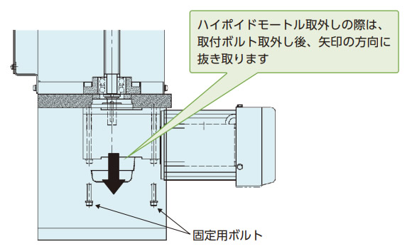
- (3) ハイポイドモートルを固定している4本のボルトを緩めます。
この時、ボルト4本すべてを取外すと、ハイポイドモートルが下方向へ抜け落ちる可能性がありますので、いずれか1本はモータの抜け防止のため、緩めた状態のままとしてください。 - (4) ハイポイドモートルが抜け落ちないよう、保持しながらすべてのボルトを取外します。
- (5) ハイポイドモートルを下方向へ抜き取ります。
- (6) ハイポイドモートル中空軸のキー位相と、ネジシャフト軸端のキー位相を合わせて、ハイポイドモートルを組付けます。
(組付けは分解時とは逆の手順で組付けてください)
4. サーボモータ付の減速機、サーボモータ保守・点検
減速機の保守・点検は添付の取扱説明書をご参照ください。また、サーボモータついては、メーカの取扱説明書をご参照ください。
4-1. 減速機交換方法
<作業手順>
- (1) 本作業を始める前には必ず電源を落としてください。
- (2) リフトマスタ本体とお客様装置を切離し、リフトマスタ本体に負荷が掛からない状態としてください。
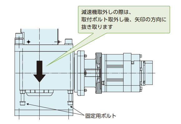
その際、リフトマスタのベースプレートを吊上げるなどして落下防止を施してください。 - (3) 減速機を固定している4本のボルトを緩めます。
この時、ボルト4本すべてを取外すと、減速機が下方向へ抜け落ちる可能性がありますので、いずれか1本は抜け防止のため、緩めた状態のままとしてください。 - (4) 減速機が抜け落ちないよう、保持しながらすべてのボルトを取外します。
- (5) 減速機を下方向へ抜き取ります。
- (6) 減速機中空軸のキー位相と、ネジシャフト軸端のキー位相を合せて、減速機を組付けます。
(組付けは分解時とは逆の手順で組付けてください)
4-2. サーボモータ交換方法
<作業手順>
- (1) 本作業を始める前には必ず電源を落としてください。
- (2) リフトマスタ本体とお客様装置を切離し、リフトマスタ本体に負荷が掛からない状態としてください。
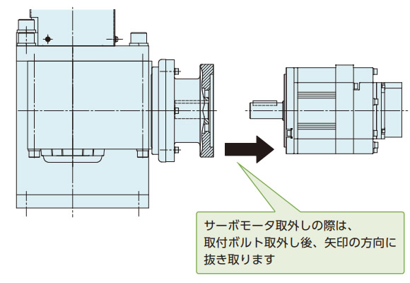
その際、リフトマスタのベースプレートを吊上げるなどして落下防止を施してください。 - (3) サーボモータを固定している4本のボルトを緩め、取外します。
- (4) サーボモータを矢印の方向へ抜き取ります。
- (5) サーボモータにキーが取付けられていることを確認し、減速機側のキー溝との位相を合わせ、サーボモータを組付けます。
(組付けは分解時とは逆の手順で組付けてください)