技術資料 カップリング 取扱
エクトフレックスカップリング NESシリーズ 取扱
1. カップリングの取扱
取扱については取扱説明書を熟読してください。
エクトフレックスカップリングNESシリーズは組立完成品(軸穴加工済)での納入になりますので、装置にそのまま組付けられます。以下の要領で軸へ取付けてください。
取付の際はカップリングに無理な力が掛かったり、落下させたりしないよう注意してください。
ディスクを固定している六角穴付ボルトは決して緩めないでください。
使用温度範囲は-30℃~100℃です。
2. カップリングの軸への取付
- (1) 取付軸の表面、カップリング取付面のゴミ、油分をウエス等できれいに拭き取ってください。
- (2) 取付軸の心出しを行い、カップリングを軸に取付けます。その際、クランプハブの端面いっぱいまで軸を挿入してください。
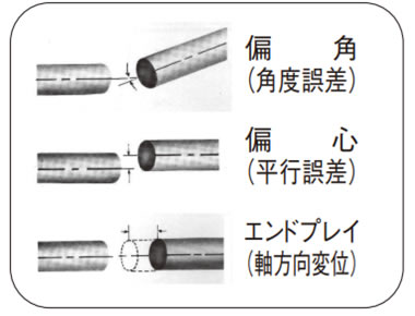
カップリングの許容偏角(角度誤差)、許容偏心(平行誤差)、許容エンドプレイ(軸方向変位)は相関関係にあり、どれか一方が増加すると他方が減少するため同時に考慮する必要があります。以下を参考に心出し調整してください。
カップリングがスペーサタイプの場合
まず偏心(平行誤差)を(グラフ1)より偏角(角度誤差)に変換します。
変換した値と偏角(角度誤差)を合算して、(グラフ2)の偏角(角度誤差)に当てはめてください。
各サイズのグラフ範囲に収まるように心出し調整してください。
(グラフ1)スペーサタイプ

(グラフ2)スペーサタイプ

カップリングがシングルタイプの場合
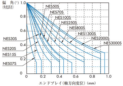
シングルタイプは偏心(平行誤差)の吸収量が極めて小さいので、主に偏角(角度誤差)とエンドプレイ(軸方向変位)を調整して心出ししてください。
(グラフ3)はカップリングの許容偏角(角度誤差)と許容エンドプレイ(軸方向変位)についての相関関係を表しています。
各サイズのグラフ範囲に収まるよう心出し調整してください。
- (3) クランプボルトが緩んでいる状態で、取付けたカップリングが回転方向・軸方向に軽い力で動くことを確認してください。もし、スムーズに動かない場合は(2)の心出しを再調整してください。
- (4) 下表の締付トルクに従ってクランプボルトを締付けてください。
(グラフ3)シングルタイプ
| 形番 | NES07 | NES15 | NES20 | NES30 | NES50 | NES70 | NES100 | NES250 | NES800 | NES1300 | NES2000 | NES3000 |
|---|---|---|---|---|---|---|---|---|---|---|---|---|
| クランプボルト サイズ |
M2 | M2 | M2.5 | M2.5 | M3 | M3 | M4 | M4 | M6 | M6 | M8 | M8 |
| 締付トルク N・m {kgf・m} |
0.50 {0.05} |
0.50 {0.05} |
1.0 {0.10} |
1.0 {0.10} |
1.9 {0.19} |
1.9 {0.19} |
3.8 {0.39} |
3.8 {0.39} |
12 {1.22} |
12 {1.22} |
30 {3.1} |
30 {3.1} |
