技術資料 カップリング 取扱
ジョーフレックスカップリング Lシリーズ 取扱
下穴品
1. 軸穴加工、キー溝加工
下穴品から穴加工、キー溝加工をする場合は、以下の手順通り行ってください。
- (1) ハブ外径をチャッキングして図1のように心出しをして加工してください。
焼結ハブタイプおよびメッキ仕様ハブは鉄系焼結合金でスチーム処理をしていますので切削用バイトには超硬材(JIS記号9-20、K-01)のご使用をお奨めします。 (L190、L225は鋳鉄です。) - (2) キー溝は爪部をさけた位置に加工してください。タップサイズと位置は表4を推奨します。
- (3) 軸穴加工公差は表5のようにすきまばめ公差を推奨します。しまりばめやパワーロックのように内部引っ張り応力の発生するような取付方法は避けてください。
図1.軸穴加工図

| はめあい | はめあい | はめあい | |||
|---|---|---|---|---|---|
| 軸公差 | 穴公差 | 軸公差 | 穴公差 | 軸公差 | 穴公差 |
| h6 h7 |
H7 | j6 j7 |
G7 | k6 k7 |
F7 |
| 焼結ハブタイプ、メッキ仕様 | アルミハブタイプ | |||||||||||||||||||
|---|---|---|---|---|---|---|---|---|---|---|---|---|---|---|---|---|---|---|---|---|
| サイズ | L035 | L050 | L070 | L075 | L090 | L095 | L099 | L100 | L110 | L150 | L190 | L225 | L050A | L070A | L075A | L090A | L095A | L100A | L110A | |
| L035F | L050F | L070F | L075F | L090F | L095F | L099F | L100F | L110F | L150F | L190F | L225F | |||||||||
| タップサイズ | M3 | M4 | M5 | M5 | M6 | M6 | M6 | M6 | M8 | M8 | M8 | M8 | M4 | M5 | M5 | M6 | M6 | M6 | M8 | |
| F(mm) | 3.0 | 8.00 | 9.5 | 10.5 | 10.5 | 12.5 | 13.5 | 12.5 | 20.5 | 17.5 | 25.5 | 25.5 | 8.0 | 9.5 | 10.5 | 10.5 | 10.5 | 17.0 | 20.5 | |
2. 取付け
- (1)両方の軸にハブとキーをはめます。この時、ハブやキーをたたき込まないでください。キーは、よくすり合わせを行ってください。
- (2) 止ネジは、2カ所で固定してください。
- (3) ハブの片側にインサートをはめます。
- (4) 両方のハブがつめの端面とインサート端面が同一平面になるように組込んでください。(図2)
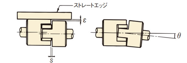
- (5) このとき、図3の様にS寸法(表6)が円周上で均等になるようにセットして偏角(角度誤差)を修正してください。許容偏角(角度誤差)θは、表6を参照してください。
- (6) また、図3のようにストレートエッジをハブ外周にあて、また約90°離れた2カ所で表6のε値以下にしてください。 インサートの寿命は、心出しの精度により大きく影響を受けます。
図2
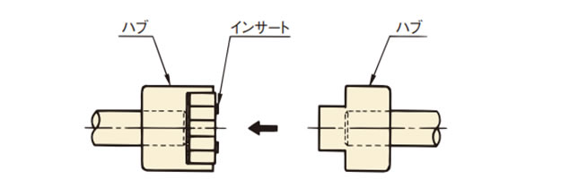
図3. 心出し図
| サイズ | 焼結ハブ | L035 | L050 | L070 | L075 | L090 | L095 | L099 | L100 | L110 | L150 | L190 | L225 |
|---|---|---|---|---|---|---|---|---|---|---|---|---|---|
| メッキ仕様 | L035F | L050F | L070F | L075F | L090F | L095F | L099F | L100F | L110F | L150F | L190F | L225F | |
| アルミハブ | L050A | L070A | L075A | L090A | L095A | L100A | L110A | ||||||
| 許容偏心(平行誤差)ε(mm) | 0.38 | 0.38 | 0.38 | 0.38 | 0.38 | 0.38 | 0.38 | 0.38 | 0.38 | 0.38 | 0.38 | 0.38 | |
| 許容偏角(角度誤差)(θ°) | S,Mタイプ | 1 | 1 | 1 | 1 | 1 | 1 | 1 | 1 | 1 | 1 | 1 | 1 |
| Hタイプ | 0.5 | 0.5 | 0.5 | 0.5 | 0.5 | 0.5 | 0.5 | 0.5 | 0.5 | 0.5 | 0.5 | 0.5 | |
| S(mm) | 標準寸法 | 0.6 | 1.9 | 1.7 | 1.7 | 1.7 | 1.7 | 1.7 | 1.9 | 2.3 | 2.0 | 2.3 | 2.3 |
| エンドプレイ(軸方向変位) | ±0.3 | ±0.5 | ±0.5 | ±0.5 | ±0.5 | ±0.5 | ±0.5 | ±0.7 | ±0.7 | ±0.7 | ±1.0 | ±1.0 | |
※アルミハブタイプはMタイプ、Hタイプでもご使用になれますが、伝達トルクはSタイプとかわりません。
- (7) 回転速度が2000r/mを超える場合は、εとθの値は表6の半分以下を推奨いたします。
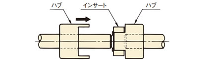
- (8) 他の取付順序として、図4のように両方のハブが爪の端面とインサート端面が同一平面になるように軸上を移動させる方法もあります。心出しの方法は、(5)・(6)と同様に行ってください。心出し後、止ネジ2ヵ所を右表(表7)の締付トルクにてしっかりと締付けてください。
- (9) 止ネジには、ゆるみ止めのため、金属用接着剤のご使用を推奨します。
(推奨接着剤:ロックタイト262)
図4
| 止ネジ サイズ |
M3 | M4 | M5 | M6 | M8 | M10 | M12 |
|---|---|---|---|---|---|---|---|
| 締付トルク N・m{kgf・m} |
0.78 {0.08} |
1.86 {0.19} |
3.63 {0.37} |
6.66 {0.68} |
16.2 {1.65} |
29.4 {3.0 } |
54.9 {5.6 } |
穴加工ハブ
1. 取付前の確認
- (1) ハブ現品に軸穴径、キーの種類(J:新JISキー普通形、E:旧JISキー2種)を表示していますので、ご発注のサイズで軸穴径、キーの種類を確認してください。
- (2) 止ネジ2個を付属しています。
- (3) 軸穴径Φ11以下は、キー溝なしですので、止ネジ2個で取付けます。
- (4) ハブを取付ける軸径の公差は、表8の推奨公差通りであることをご確認ください。
| はめあい | はめあい | はめあい | |||
|---|---|---|---|---|---|
| 軸公差 | 穴公差 | 軸公差 | 穴公差 | 軸公差 | 穴公差 |
| h6 h7 |
H7 | j6 j7 |
G7 | k6 k7 |
+ 0.040 + 0.015 |
2. 取付け
上記の下穴品の取付けの項を参照してください。
3. 使用環境
- ・なるべく風通しの良いほこりや湿気の少ない所で使用してください。
- ・腐食性の液体やガスのある場所、引火性・爆発性のある場所でのご使用は避けてください。
- ・屋外でのご使用は避けてください。
4. 点検
実際の運転に入って1~2時間後に、偏角(角度誤差)と偏心(平行誤差)を再チェックしてください。
また、定期的(例えば半年~1年ごと)に部品の異常やインサートの摩耗を確認してください。
インサートは消耗品です。定期的に交換をしてください。
