Shock Guard coupling TGB Series Major Specifications
Model No. :TGB110-LC

[Click to enlarge ]
PDF Outline Drawing
CAD data in DXF format
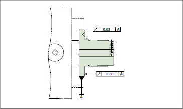
TGB110-LC
(Click here for a list of all DXF files )
3D CAD data
Standard Price
Contact us for details.
Delivery
Contact us for details.
| ※ | The CAD data contained herein is made available to you via the CAD drawing library; PARTcommunity is provided by CADENAS WEB2CAD Co. |
| ※ | Please direct your inquiries regarding the CAD data service or PARTcommunity to: CADENAS WEB2CAD Co. TEL: +81 (3) 5961-5031 FAX: +81 (3) 5961-5032 |
Catalogs ・Instruction Manuals
Transmission Capacity and Dimensions Units :mm
| Set torque range N・m |
Max. Rotation Speed r/min |
Color of spring | Shock Guard | Coupling | A | B | C | D | E | F | G | H | I | ||||
|---|---|---|---|---|---|---|---|---|---|---|---|---|---|---|---|---|---|
| Plain bore Diameter | Smallest Shaft Bore Diameter | Maximum Shaft Bore Diameter | Plain bore Diameter | Smallest Shaft Bore Diameter | Maximum Shaft Bore Diameter | ||||||||||||
| 686~1960 | 100 | Yellow | 52 | 54 | 110 | 38 | 40 | 113 | 303 | 100 | 195 | 105 | 99.2 | 21.9 | 473.4 | 157 | 345 |
| J | K | L | M×N×Quantity | O Screw diameter x pitch |
P Screw diameter x length |
Q Screw diameter x length |
R | S | T | U Screw diameter x length |
Coupling model No. or sprocket used | Mass kg ※1 |
Moment of Inertia ×10-2kg・m2 ※1 |
GD2 ×10-2kgf・m2 ※1 |
|---|---|---|---|---|---|---|---|---|---|---|---|---|---|---|
| 278 | 266 | 155 | M16×45ℓ×6 | M160×3 | M16×45 | M12×20 | 8 | 7 | 6 | M10×20 | RS120-36 | 130.5 | 314.15 | 1256.61 |
※1. The weight, moment of inertia, and GD2 are given for the maximum bore diameter.
shaft bore machining
・The boss has undergone a thermal refining process.
(1)Loosen the adjusting nut and disassemble all the parts. Remove the snap ring for the shaft and center plate as well. When doing so, make sure each part is free of dust.
(2)Chuck the outer diameter of the boss flange portion and center at the boss portion.
(3)Machine the keyway just under the clearance of the torque scale.
(4)Perform tap machining for the set screw at two locations, the clearance of the torque scale and 90° from that point. The tap located at the 90° position will be machined over the torque scale.
(5)Apply lubricating grease between the ball and bearing during reassembly after machining the shaft bore.
Contact Information
Online Inquiries
For inquiries in English, visit the Inquiries page on our Tsubaki Group website.

