ECHT-FLEX Coupling NEF Series Major Specifications
Model No. :NEF25W-B40P2XNH40JD2
Equivalent Taper-Lock hub model no. : NEF25W-H40XNH40JD2
[Click to enlarge ]
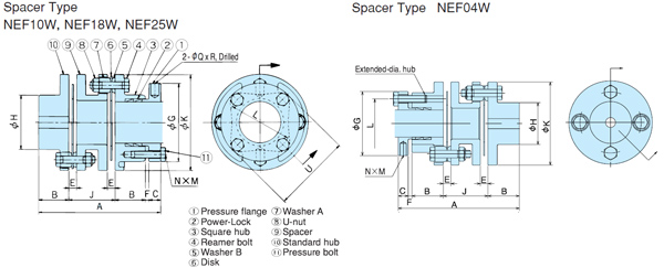
This drawing shows one-side Power-Lock clamping.
Refer to the PDF outline drawings or contact us for detail drawings.
PDF Outline Drawing
CAD data in DXF format
Contact us for details.
(Click here for a list of all DXF files )
3D CAD data
Contact us for details.
Standard Price
Contact us for details.
Delivery
Contact us for details.
Catalogs ・Instruction Manuals
- E-Book Catalog (Japanese)
- E-Book Catalog (English)
- Instruction Manuals (Japanese) (Single type / Spacer type )
- Instruction Manuals (English) (Single type / Spacer type )
- Instruction Manuals (Japanese) (Long spacer type )
- Instruction Manuals (English) (Long spacer type )
- Instruction Manuals (Japanese) (Power-Lock specifications )
- Instruction Manuals (English) (Power-Lock specifications )
- Instruction Manuals (Japanese) (Clamp fastening )
- Instruction Manuals (English) (Clamp fastening )
- Instruction Manuals (Japanese) (Taper-Lock fastening )
- Instruction Manuals (English) (Taper-Lock fastening )
Transmission Capacity and Dimensions
| Allowable Torque | Max. Rotation Speed r/min |
Plain Bore d |
Standard Stock Shaft Bore Dia. | Maximum Shaft Bore Diameter | Torsional Rigidity | Axial Spring Constant | ||||
|---|---|---|---|---|---|---|---|---|---|---|
| N・m | {kgf・m} | Locking Device | Keyway | N・m/rad | {kgf・m/rad} | N/mm | {kgf/mm} | |||
| 245 | 25 | 15000 | 15 | 18~42 | 42 | 42 | 12.7×10⁴ | 1.3×10⁴ | 78.4 | 8 |
| A | B | C | F | E | G | H | J | K | L | M | N | Q | R | U |
|---|---|---|---|---|---|---|---|---|---|---|---|---|---|---|
| 135 | 33.5 | 12 | 3 | 11.2 | 78 | 61 | 53 | 104 | 64 | M8×28L | 4 | 8 | 13 | 78.3 |
| Allowable Misalignment | Mass kg |
Moment of Inertia kg・m2 |
GD2 {kgf・cm2} |
||
|---|---|---|---|---|---|
| Angular Misalignment deg |
Parallel Misalignment | Axial Displacement (Note) | |||
| 2 | 0.7 | ±2.8 | 3.4 | 44 | 178 |
Note)
1.※The hub and pressure flange for sizes within the standard stock shaft bore diameter range have pre-machined shaft bores for two-row type Power-Locks.
2.※The maximum shaft bore diameter includes a margin for a Power-Lock.
3.The maximum speed depends on the transmission capacity of the coupling. No balance adjustment has been conducted.
4.The weight, moment of inertia, and GD2 are given for the maximum bore diameter.
5.The allowable axial displacement is based on the assumption that the angular misalignment is 0.
6.Tsubaki can make sizes NEF45 or higher with a Power-Lock. Request drawings for more information.
7.Contact us to verify the strength when mounting on a hollow shaft.
Contact Information
Online Inquiries
For inquiries in English, visit the Inquiries page on our Tsubaki Group website.
